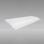
Наконечник литейного канала является ключевым компонентом машины для литья и прокатки алюминиевой ленты, и его качество напрямую влияет на толщину, качество и выход алюминиевой ленты. Правильная установка и выравнивание наконечника литейной машины определяют равномерность распределения расплава, качество поверхности полосы и допуски на размеры по всей ширине литого изделия. В данном руководстве рассматриваются протоколы предварительного нагрева, процедуры сборки, параметры выравнивания и методы устранения неисправностей, основанные на устоявшейся промышленной практике и металлургических принципах.
Что такое наконечник литейного колеса и почему он важен при непрерывном литье?
Наконечник литьевого стана (также называемый литьевым соплом или кастертипом) — это огнеупорный элемент, расположенный между наливным ящиком (передним ящиком) и вращающимися литьевыми валками в двухвалковом непрерывном литьевом стане. Его основная функция заключается в равномерном распределении расплавленного алюминия в зоне контакта валков, формируя однородный фронт затвердевания, что позволяет получать полосу с постоянной толщиной и качеством поверхности.
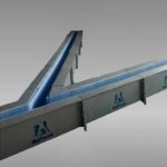
Литейный наконечник и сопло состоят из верхней и нижней пластин, боковых пластин и средней разделительной пластины. Форма, размеры и положение средней разделительной пластины зафиксированы в процессе изготовления для обеспечения равномерного распределения потока по всей ширине литья.
Внутренняя полость литейной сопловой пластины и шунтирующей пластины подвергаются специальной обработке нитридом бора, что позволяет обеспечить эффективную защиту от эрозии под воздействием расплавленного алюминия при высоких температурах, повысить износостойкость, обеспечить высокую производительность литейной сопловой пластины, а также эффективно предотвратить появление чёрных пятен на алюминиевой пластине и повысить гладкость её поверхности.
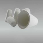
Наконечник кастера из керамического волокна AdTech Используется для формирования кристаллической структуры и контроля размеров алюминиевых листов на линии литья. В его составе применяется композитный материал с наноразмерными волокнами, обработанный с помощью высокоточного оборудования. Насадки и сопла для литья AdTech отличаются умеренной плотностью, хорошей теплоизоляцией, точными размерами, высокой стойкостью к окислению и низкой деформацией. Правильное использование насадки для литья является важным этапом непрерывного литья.
Каковы основные компоненты узла ролика?
| Компонент | Материал | Функция |
|---|---|---|
| Пластина верхней губы | Композит из керамического волокна / с покрытием из борнитрида | Образует верхнюю границу канала плавления; определяет контакт с верхним валом |
| Нижняя губная пластина | Композит из керамического волокна / с покрытием из борнитрида | Образует нижнюю границу; выдерживает вес расплава |
| Боковые перегородки (боковые пластины) | Силикат кальция высокой плотности или керамическое волокно | Герметизирует боковые края; предотвращает утечку расплава |
| Средняя разделительная пластина (шунтирующая пластина) | Керамика с покрытием BN | Разделяет поток расплава на параллельные каналы для равномерного распределения |
| Прокладки / уплотнительные ленты | Керамическая бумага (1–3 мм) | Предотвращает попадание воздуха и просачивание расплава в местах соединений |
Каждый компонент должен соответствовать строгим допускам на размеры. Отклонение по плоскостности кромки, превышающее 0,10 мм по всей длине кромки шириной 1800 мм, может привести к колебаниям размеров готовой ленты в пределах ±0,02 мм — этого достаточно, чтобы привести к браку при производстве фольги.
Как подготовить наконечник ролика перед установкой?
Подготовка — это не просто дополнительный этап, а самый важный этап, позволяющий избежать брака при запуске. Влага, впитанная в материалы из керамического волокна, при контакте с расплавом алюминия температурой 680–720 °C образует пар, что приводит к появлению пористости, микроотверстий и, в крайних случаях, к взрывному отслоению поверхности кромки.
Какова правильная процедура предварительного нагрева литейных сопел?
Передняя камера и узел сопла для литья предварительно сушатся в сушильной печи при температуре около 200 °C в течение двух часов, а затем хранятся в сушильной камере при температуре около 110 °C. Подготовка линии литья и прокатки должна быть надлежащим образом завершена до того, как узел сопла для литья будет извлечен из сушильной камеры.
Приведенная ниже схема предварительного нагрева доказала свою эффективность при работе с различными семействами сплавов (серии 1xxx, 3xxx, 8xxx):
| Этап | Температура (°C) | Продолжительность | Цель |
|---|---|---|---|
| Начальный участок | Амбиент → 110 | 30–40 минут | Удаляет поверхностную влагу без термического шока |
| Промежуточная остановка | 110 | Не менее 30 минут | Обеспечивает достижение заданной температуры сердцевины; выравнивает градиент влажности |
| Заключительный подъем | 110 → 200 | 20–30 минут | Удаляет химически связанную воду из структуры волокна |
| Замочить | 200 ± 10 | 60–120 мин | Гарантирует остаточную влажность < 0,1% по массе |
| Holding (standby) | 110 | Until installation | Prevents re-absorption; must not exceed 8 hours |
Key point: Ramp rates above 5 °C/min risk micro-cracking in thick-section lip plates (≥ 25 mm). Controlled heating matters more than peak temperature.
For operations requiring high-performance ceramic fiber caster tips with low residual moisture characteristics, material selection at the procurement stage substantially reduces preheating risk.
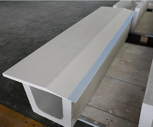
Совет по питателю литейного оборудования
Как установить и отрегулировать наконечник ролика на прокатном стане?
After the casting tip and nozzle is assembled and preheated and before it is assembled in the casting and rolling mill, all preparations should be made, and the casting tip and nozzle should be installed at the fastest speed to avoid heat loss and inhalation of moisture.
Пошаговая инструкция по установке
- Clean the platform thoroughly. After the casting nozzle plate is placed on the platform, tighten the fixing screws. No debris is allowed on the casting nozzle plate platform, fixture, and outer surface. Otherwise, the position of the casting nozzle plate will be inaccurate. Therefore, before the casting nozzle plate is fixed on the platform, it should be thoroughly cleaned. Even a 0.5 mm particle trapped under the lip plate can tilt the entire nozzle, producing a strip that is thicker on one edge.
- Position the tip assembly on the carriage. Use alignment pins or dowels to index the nozzle to the pre-set centerline. The tip centerline must coincide with the roll bite centerline within ± 0.5 mm laterally.
- Set the tip-to-roll gap (setback). This is the distance from the lip edge to the narrowest point of the roll gap. Typical setback values:
| Strip Thickness Target | Recommended Setback | Tip Lip Thickness |
|---|---|---|
| 6–7 mm | 48–52 mm | 1.5–2.0 mm |
| 7–9 mm | 52–58 mm | 2.0–2.5 mm |
| 9–12 mm | 55–62 mm | 2.5–3.0 mm |
Setback that is too short causes premature freezing inside the nozzle cavity (plugging). Setback that is too long reduces the solidification contact arc, producing strip with a mushy center and poor mechanical properties.
- Adjust the vertical position. The upper lip should sit approximately 0.5–1.0 mm above the roll pass line; the lower lip approximately 0.5 mm below. This slight asymmetry accounts for gravitational melt head pressure and promotes a symmetrical solidification shell.
- Seal all joints. Apply ceramic paper gaskets between the tip and the headbox flange. Tighten fasteners in a cross-pattern sequence to distribute clamping force uniformly. A torque of 8–12 N·m is typical for M8 stainless steel bolts on ceramic fiber assemblies — overtightening crushes the fiber structure and creates leak paths.
- Verify gap uniformity with feeler gauges. Insert 0.05 mm feeler gauges between each lip and the corresponding roll surface at 150 mm intervals across the full width. Deviation should not exceed ± 0.03 mm. Shim as necessary.
Каковы наиболее распространённые дефекты наконечников роликов и как их предотвратить?
Understanding failure modes is essential for reducing scrap rates and extending tip service life. The table below summarizes the most frequently encountered issues in production:
| Дефект | Основная причина | Observable Symptom | Corrective Action |
|---|---|---|---|
| Edge cracking of strip | Misaligned side dam; excessive tip-to-roll pressure at edges | Ragged strip edges; edge trim loss > 8% | Re-align side dams; verify cheek plate parallelism |
| Centerline segregation | Blocked or displaced shunt plate channel | Hard spot or dark streak at strip center | Inspect shunt plate for aluminum buildup; replace if BN coating is eroded |
| Surface black spots | Insufficient BN treatment; tip material degradation | Scattered dark inclusions on strip surface | Use high-quality BN-coated casting nozzles with verified coating thickness ≥ 0.15 mm |
| Gauge variation across width | Uneven tip-to-roll gap; debris under lip plate | Strip thickness profile shows wedge or crown | Re-clean platform; re-shim lip plates to ± 0.03 mm tolerance |
| Tip erosion / short service life | Melt temperature exceeding 730 °C; high Mg-alloy corrosion | Visible pitting on lip contact face after < 20 hours | Lower pouring temperature to 690–710 °C; select erosion-resistant tip material |
| Moisture-related porosity | Inadequate preheating or prolonged exposure before install | Pinhole clusters on strip surface in first 5–10 minutes | Follow strict preheat protocol (see above); minimize ambient exposure to < 3 minutes |
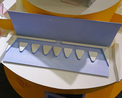
Конструкция и компоненты наконечника литницы для расплавленного алюминия
Как конструкция наконечника ролика влияет на качество полосы?
The geometry of the internal flow channel governs melt velocity distribution. A well-designed shunt plate creates equal mass flow per unit width — typically targeting a flow velocity variation of less than ± 5% across the nozzle exit. Flow imbalance generates thermal gradients at the solidification front, which manifest as gauge variation, surface ripples, or micro-segregation banding in the finished strip.
Lip taper angle also plays a measurable role. A convergent taper of 1.5–3° on the exit section accelerates melt slightly, stabilizing the meniscus at the roll contact point. Excessive taper (> 4°) can induce turbulence and oxide entrainment.
Material thermal conductivity must be low enough to prevent premature solidification inside the nozzle but high enough to survive thermal shock during startup. AdTech’s nano-scale fiber composite achieves a thermal conductivity of approximately 0.15–0.25 W/m·K at 700 °C, which sits in the optimal range for 1xxx and 8xxx alloy casting.
For continuous caster operations producing aluminum cast strip for downstream foil rolling, maintaining tip dimensional stability over extended campaigns (40–80 hours) is non-negotiable. Tip deformation under sustained thermal load should remain below 0.3% linear shrinkage.
Как часто следует заменять наконечники роликов?
Replacement intervals depend on alloy family, casting speed, and melt cleanliness. General guidelines based on accumulated industry data:
- 1xxx / 1050, 1060, 1070 alloys: 50–80 hours typical service life with clean melt
- 3xxx / 3003, 3105 alloys: 35–55 hours due to higher Mn content accelerating erosion
- 8xxx / 8011, 8079 alloys: 40–65 hours; Fe-Si intermetallics can abrade BN coating
- 5xxx / 5052 alloys (high Mg): 20–35 hours; Mg vapor attack degrades ceramic fiber matrix
These numbers assume proper дегазация и фильтрация upstream of the headbox. Inadequate melt treatment — particularly hydrogen content above 0.15 mL/100g Al — accelerates tip degradation and should be addressed at source rather than compensated by more frequent tip changes.
Заключение
Proper use of the caster tip encompasses material selection, controlled preheating, precise mechanical alignment, and disciplined process monitoring during the cast. Each variable interacts with the others: a perfectly aligned tip will still fail if moisture was not fully driven out, and a dry, well-preheated tip will produce scrap if the setback distance is wrong. The procedures outlined here represent a consolidated framework. Operators should adapt specific parameters — temperatures, setback values, torque specifications — to their particular mill configuration and alloy mix, while maintaining the underlying principles of cleanliness, dimensional precision, and thermal control throughout the entire caster tip lifecycle.
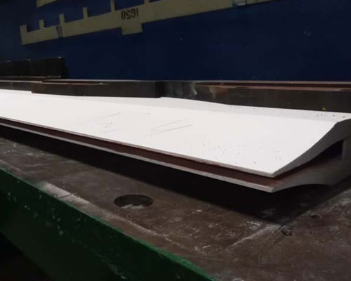
Керамический наконечник ролика
Часто задаваемые вопросы
1. What is a caster tip in aluminum strip casting?
A caster tip is the nozzle assembly that guides molten aluminum into the roll gap and helps control strip thickness, shape, and surface quality.
2. Why is preheating a caster tip necessary?
Preheating removes moisture and reduces thermal shock, helping prevent cracks, steam-related defects, and unstable casting during startup.
3. What temperature should a caster tip be preheated to?
A caster tip is typically pre-dried at about 200°C for 2 hours and then kept at around 110°C before installation.
4. How quickly should a preheated caster tip be installed??
It should be installed as quickly as possible after removal from the drying box to avoid heat loss and moisture absorption.
5. What happens if the caster tip platform is not clean?
Debris on the platform can shift the tip position, causing poor alignment, thickness variation, leakage, or strip surface defects.
6. What causes black spots on aluminum strip?
Black spots are often caused by poor nozzle condition, contamination, or inadequate boron nitride protection inside the casting tip.
7. How do you know a caster tip is misaligned?
Common signs include uneven strip thickness, unstable metal flow, edge defects, surface marks, and reduced yield.
8. How does boron nitride improve caster tip performance?
Boron nitride reduces aluminum sticking, improves wear resistance, protects the inner cavity, and helps produce a smoother strip surface.
9. How often should a caster tip be replaced?
Replacement depends on alloy, temperature, casting speed, and wear condition, but the tip should be changed once deformation or erosion affects strip quality.
10. What is the main purpose of a caster tip?
The main purpose of a caster tip is to distribute molten aluminum evenly and support stable crystallization in continuous casting.