The caster tip is a key component of the aluminum strip casting and rolling machine, and its quality directly affects the thickness, quality, and yield of the aluminum strip. Proper caster tip installation and alignment determine melt distribution uniformity, strip surface finish, and dimensional tolerance across the full width of the cast product. This guide covers preheating protocols, assembly procedures, alignment parameters, and troubleshooting methods based on established industrial practice and metallurgical principles.
What Is a Caster Tip and Why Does It Matter in Continuous Casting?
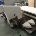
A caster tip (also called a casting nozzle or castertip) is the refractory component positioned between the headbox (front box) and the rotating casting rolls in a twin-roll continuous caster. Its primary function is to distribute molten aluminum evenly into the roll bite, forming a uniform solidification front that produces strip with consistent gauge and surface quality.
The casting tip and nozzle include the upper and lower plates, side plates, and the middle dividing plate. The shape, size, and position of the middle dividing plate have been fixed during manufacturing to ensure balanced flow distribution across the casting width.
The inner cavity of the casting nozzle plate and the shunt plate are all specially treated with boron nitride, which can effectively protect against erosion by high-temperature aluminum liquid, increase abrasion resistance, make the casting nozzle plate achieve high performance, and effectively prevent the aluminum plate from developing black spots, while increasing the smoothness of the surface of the aluminum plate.
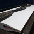
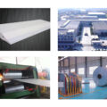
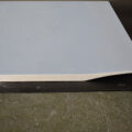
AdTech ceramic fiber castertip is used for crystallization forming and size control of aluminum plate in the casting production line. It adopts nano-scale fiber composite material processed by high-precision equipment. AdTech casting tips and nozzles have moderate density, good thermal insulation, precise size, high oxidation resistance, and low deformation. How to Use Caster Tip correctly is an important step in continuous casting.
If your project requires the use of Ceramic Fiber Blanket, you can contact us for a free quote.
What Are the Main Components of a Caster Tip Assembly?
| Component | Material | Function |
|---|---|---|
| Upper lip plate | Ceramic fiber composite / BN-coated | Forms upper boundary of melt channel; controls contact with top roll |
| Lower lip plate | Ceramic fiber composite / BN-coated | Forms lower boundary; supports melt pool weight |
| Side dams (cheek plates) | High-density calcium silicate or ceramic fiber | Seals lateral edges; prevents melt leakage |
| Middle dividing plate (shunt plate) | BN-coated ceramic | Splits melt flow into parallel channels for uniform distribution |
| Gasket / seal strips | Ceramic paper (1–3 mm) | Prevents air ingress and melt seepage at joints |
Each component must meet tight dimensional tolerances. A lip plate flatness deviation exceeding 0.10 mm across a 1800 mm wide tip can produce gauge variation of ±0.02 mm in the finished strip — enough to cause rejection in foilstock applications.
How to Prepare a Caster Tip Before Installation?
Preparation is not optional — it is the single most critical phase for avoiding startup scrap. Moisture absorbed by ceramic fiber materials generates steam on contact with 680–720 °C aluminum melt, causing porosity, pinhole defects, and in severe cases, explosive spalling of the lip surface.
What Is the Correct Preheating Procedure for Casting Nozzles?
The front box and the casting tip nozzle assembly are pre-dried for two hours in a drying oven at about 200 °C, and stored in the drying box at about 110 °C. The preparation of the casting-rolling production line should be properly completed before the casting nozzle plate assembly is taken out of the drying box.
The following preheating schedule has proven effective across multiple alloy families (1xxx, 3xxx, 8xxx series):
| Stage | Temperature (°C) | Duration | Purpose |
|---|---|---|---|
| Initial ramp | Ambient → 110 | 30–40 min | Drives off surface moisture without thermal shock |
| Intermediate hold | 110 | 30 min minimum | Ensures core reaches temperature; equilibrates moisture gradient |
| Final ramp | 110 → 200 | 20–30 min | Removes chemically bound water from fiber structure |
| Soak | 200 ± 10 | 60–120 min | Guarantees residual moisture < 0.1% by weight |
| Holding (standby) | 110 | Until installation | Prevents re-absorption; must not exceed 8 hours |
Key point: Ramp rates above 5 °C/min risk micro-cracking in thick-section lip plates (≥ 25 mm). Controlled heating matters more than peak temperature.
For operations requiring high-performance ceramic fiber caster tips with low residual moisture characteristics, material selection at the procurement stage substantially reduces preheating risk.
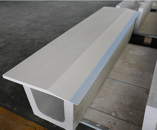
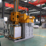
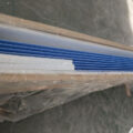
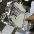
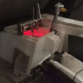
Foundry Feeder Tip
How to Install and Align a Caster Tip on the Rolling Mill?
After the casting tip and nozzle is assembled and preheated and before it is assembled in the casting and rolling mill, all preparations should be made, and the casting tip and nozzle should be installed at the fastest speed to avoid heat loss and inhalation of moisture.
Step-by-Step Installation Procedure
- Clean the platform thoroughly. After the casting nozzle plate is placed on the platform, tighten the fixing screws. No debris is allowed on the casting nozzle plate platform, fixture, and outer surface. Otherwise, the position of the casting nozzle plate will be inaccurate. Therefore, before the casting nozzle plate is fixed on the platform, it should be thoroughly cleaned. Even a 0.5 mm particle trapped under the lip plate can tilt the entire nozzle, producing a strip that is thicker on one edge.
- Position the tip assembly on the carriage. Use alignment pins or dowels to index the nozzle to the pre-set centerline. The tip centerline must coincide with the roll bite centerline within ± 0.5 mm laterally.
- Set the tip-to-roll gap (setback). This is the distance from the lip edge to the narrowest point of the roll gap. Typical setback values:
| Strip Thickness Target | Recommended Setback | Tip Lip Thickness |
|---|---|---|
| 6–7 mm | 48–52 mm | 1.5–2.0 mm |
| 7–9 mm | 52–58 mm | 2.0–2.5 mm |
| 9–12 mm | 55–62 mm | 2.5–3.0 mm |
Setback that is too short causes premature freezing inside the nozzle cavity (plugging). Setback that is too long reduces the solidification contact arc, producing strip with a mushy center and poor mechanical properties.
- Adjust the vertical position. The upper lip should sit approximately 0.5–1.0 mm above the roll pass line; the lower lip approximately 0.5 mm below. This slight asymmetry accounts for gravitational melt head pressure and promotes a symmetrical solidification shell.
- Seal all joints. Apply ceramic paper gaskets between the tip and the headbox flange. Tighten fasteners in a cross-pattern sequence to distribute clamping force uniformly. A torque of 8–12 N·m is typical for M8 stainless steel bolts on ceramic fiber assemblies — overtightening crushes the fiber structure and creates leak paths.
- Verify gap uniformity with feeler gauges. Insert 0.05 mm feeler gauges between each lip and the corresponding roll surface at 150 mm intervals across the full width. Deviation should not exceed ± 0.03 mm. Shim as necessary.
What Are Common Caster Tip Defects and How to Prevent Them?
Understanding failure modes is essential for reducing scrap rates and extending tip service life. The table below summarizes the most frequently encountered issues in production:
| Defect | Root Cause | Observable Symptom | Corrective Action |
|---|---|---|---|
| Edge cracking of strip | Misaligned side dam; excessive tip-to-roll pressure at edges | Ragged strip edges; edge trim loss > 8% | Re-align side dams; verify cheek plate parallelism |
| Centerline segregation | Blocked or displaced shunt plate channel | Hard spot or dark streak at strip center | Inspect shunt plate for aluminum buildup; replace if BN coating is eroded |
| Surface black spots | Insufficient BN treatment; tip material degradation | Scattered dark inclusions on strip surface | Use high-quality BN-coated casting nozzles with verified coating thickness ≥ 0.15 mm |
| Gauge variation across width | Uneven tip-to-roll gap; debris under lip plate | Strip thickness profile shows wedge or crown | Re-clean platform; re-shim lip plates to ± 0.03 mm tolerance |
| Tip erosion / short service life | Melt temperature exceeding 730 °C; high Mg-alloy corrosion | Visible pitting on lip contact face after < 20 hours | Lower pouring temperature to 690–710 °C; select erosion-resistant tip material |
| Moisture-related porosity | Inadequate preheating or prolonged exposure before install | Pinhole clusters on strip surface in first 5–10 minutes | Follow strict preheat protocol (see above); minimize ambient exposure to < 3 minutes |
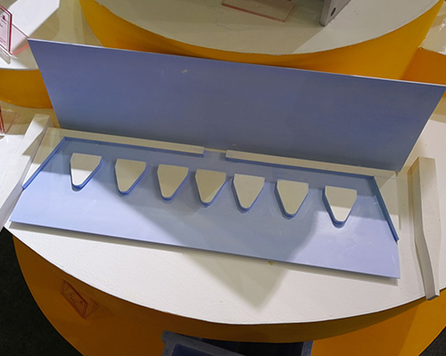
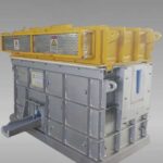
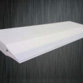
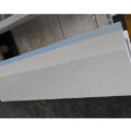
Molten Aluminum Caster Tip Structure and Components
How Does Caster Tip Design Affect Strip Quality?
The geometry of the internal flow channel governs melt velocity distribution. A well-designed shunt plate creates equal mass flow per unit width — typically targeting a flow velocity variation of less than ± 5% across the nozzle exit. Flow imbalance generates thermal gradients at the solidification front, which manifest as gauge variation, surface ripples, or micro-segregation banding in the finished strip.
Lip taper angle also plays a measurable role. A convergent taper of 1.5–3° on the exit section accelerates melt slightly, stabilizing the meniscus at the roll contact point. Excessive taper (> 4°) can induce turbulence and oxide entrainment.
Material thermal conductivity must be low enough to prevent premature solidification inside the nozzle but high enough to survive thermal shock during startup. AdTech’s nano-scale fiber composite achieves a thermal conductivity of approximately 0.15–0.25 W/m·K at 700 °C, which sits in the optimal range for 1xxx and 8xxx alloy casting.
For continuous caster operations producing aluminum cast strip for downstream foil rolling, maintaining tip dimensional stability over extended campaigns (40–80 hours) is non-negotiable. Tip deformation under sustained thermal load should remain below 0.3% linear shrinkage.
How Often Should Caster Tips Be Replaced?
Replacement intervals depend on alloy family, casting speed, and melt cleanliness. General guidelines based on accumulated industry data:
- 1xxx / 1050, 1060, 1070 alloys: 50–80 hours typical service life with clean melt
- 3xxx / 3003, 3105 alloys: 35–55 hours due to higher Mn content accelerating erosion
- 8xxx / 8011, 8079 alloys: 40–65 hours; Fe-Si intermetallics can abrade BN coating
- 5xxx / 5052 alloys (high Mg): 20–35 hours; Mg vapor attack degrades ceramic fiber matrix
These numbers assume proper degassing and filtration upstream of the headbox. Inadequate melt treatment — particularly hydrogen content above 0.15 mL/100g Al — accelerates tip degradation and should be addressed at source rather than compensated by more frequent tip changes.
Conclusion
Proper use of the caster tip encompasses material selection, controlled preheating, precise mechanical alignment, and disciplined process monitoring during the cast. Each variable interacts with the others: a perfectly aligned tip will still fail if moisture was not fully driven out, and a dry, well-preheated tip will produce scrap if the setback distance is wrong. The procedures outlined here represent a consolidated framework. Operators should adapt specific parameters — temperatures, setback values, torque specifications — to their particular mill configuration and alloy mix, while maintaining the underlying principles of cleanliness, dimensional precision, and thermal control throughout the entire caster tip lifecycle.
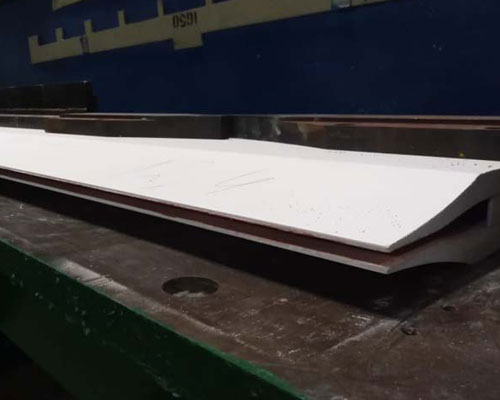
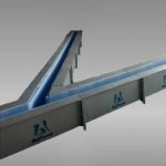
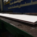
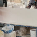
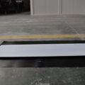
Ceramic Caster Tip
FAQ
1. What is a caster tip in aluminum strip casting?
A caster tip is the nozzle assembly that guides molten aluminum into the roll gap and helps control strip thickness, shape, and surface quality.
2. Why is preheating a caster tip necessary?
Preheating removes moisture and reduces thermal shock, helping prevent cracks, steam-related defects, and unstable casting during startup.
3. What temperature should a caster tip be preheated to?
A caster tip is typically pre-dried at about 200°C for 2 hours and then kept at around 110°C before installation.
4. How quickly should a preheated caster tip be installed??
It should be installed as quickly as possible after removal from the drying box to avoid heat loss and moisture absorption.
5. What happens if the caster tip platform is not clean?
Debris on the platform can shift the tip position, causing poor alignment, thickness variation, leakage, or strip surface defects.
6. What causes black spots on aluminum strip?
Black spots are often caused by poor nozzle condition, contamination, or inadequate boron nitride protection inside the casting tip.
7. How do you know a caster tip is misaligned?
Common signs include uneven strip thickness, unstable metal flow, edge defects, surface marks, and reduced yield.
8. How does boron nitride improve caster tip performance?
Boron nitride reduces aluminum sticking, improves wear resistance, protects the inner cavity, and helps produce a smoother strip surface.
9. How often should a caster tip be replaced?
Replacement depends on alloy, temperature, casting speed, and wear condition, but the tip should be changed once deformation or erosion affects strip quality.
10. What is the main purpose of a caster tip?
The main purpose of a caster tip is to distribute molten aluminum evenly and support stable crystallization in continuous casting.
Related posts:
 Caster Tip for Aluminum Strip Casting
 Caster Tip for Aluminum Casting
 Aluminum Silicate Caster Tip
 Caster Tip for Continuous Casting
 Aluminum Silicate Ceramic Caster Tip
 Distribution Caster Tips
 Casting Rolling Technology
 Aluminum Silicate Caster Tips
 Caster Tip and Nozzle
 Caster Tip Nozzle
 Aluminum Strip Continuous Casting Process
 Caster Tips and Nozzles
 Caster Nozzle for Aluminum
 Caster Feeding Nozzle
 Alumina Ceramic Foam Filter: The Complete Buyer’s Guide for Molten Aluminum Filtration