What Is the Ceramic Foam Filter Placement Method in Aluminum Casting?
In aluminum continuous casting and rolling operations, melt cleanliness determines everything downstream — strip surface quality, mechanical properties, internal soundness, and final product yield. The ceramic foam filter is the component that does the heavy lifting in removing oxide inclusions, slag particles, and other non-metallic contaminants from the aluminum melt before it reaches the casting machine.
But the filter itself is only half the equation. How it is placed — its orientation, seating position, seal integrity, and alignment within the filtration equipment — directly controls whether it performs at full efficiency or allows contaminated metal to bypass into the casting system. The ceramic foam filter placement method is not a minor installation detail. It is a process variable that affects filtration rate, inclusion capture efficiency, filter service life, and ultimately the quality of every ton of aluminum that passes through the line.
This guide focuses specifically on ceramic foam filter placement within AdTech’s product — the most widely used inline filtration equipment in aluminum casting operations worldwide. Whether you are installing filters for the first time on a new line or troubleshooting filtration performance on an existing one, the placement principles covered here apply directly to your operation.
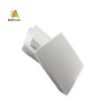
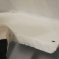
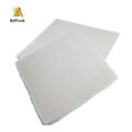
Close-up of a ceramic foam filter plate with uniform pore structure, designed for effective removal of inclusions in molten aluminum.
How Does a Plate-Type Filtering Unit Work?
Before discussing placement technique, it helps to understand the equipment the filter sits inside.
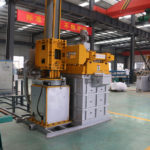
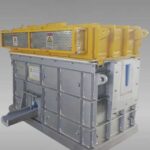
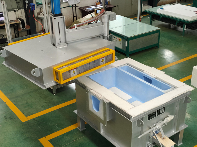
A plate-type filtering unit — sometimes called a CFF box or filter box — is a thermally insulated, refractory-lined vessel designed to hold a flat ceramic foam filter in a horizontal position within the aluminum melt transfer system. It sits inline between the holding furnace (or degassing unit) and the casting machine, typically integrated into the launder system that carries molten aluminum from one process stage to the next.
The basic operating principle is straightforward: molten aluminum enters the filter box through an inlet chamber, passes downward through the ceramic foam filter under gravity and metallostatic pressure, and exits through an outlet chamber into the downstream launder. As the melt passes through the filter’s open-cell ceramic structure, oxide inclusions, slag particles, and other non-metallic contaminants are captured by the tortuous pore network through a combination of mechanical interception, surface adhesion, and cake filtration on the filter face.
The key components of a typical plate-type filtering unit include:
- Insulated steel shell with refractory lining to maintain melt temperature during filtration
- Filter seat — a precision-machined refractory ledge that supports the ceramic foam filter at the correct height and provides a seal between the inlet and outlet chambers
- Inlet and outlet chambers separated by the filter, with launder connections on each side
- Lid or cover for thermal insulation and to prevent atmospheric oxidation of the melt surface
- Preheat burner port to bring the unit and filter up to operating temperature before the melt is introduced
The filter box is designed so that the ceramic foam filter can be replaced between casting campaigns. This makes filter placement a routine operational task — one that the casting crew performs regularly. Getting it right every time is what separates consistent melt quality from unpredictable results.
Why Is Correct Filter Placement Inside the Filter Box So Critical?
The ceramic foam filter placement method inside a plate-type filtering unit matters for several specific, measurable reasons:
Bypass prevention. If the filter does not seat properly against the refractory ledge, unfiltered metal can flow around the edges of the filter rather than through it. Even a 2–3 mm gap between the filter edge and the seat allows a significant volume of unfiltered melt to bypass into the outlet chamber. This bypass flow carries exactly the inclusions and slag particles that the filter was supposed to remove. The result is contaminated metal reaching the caster tip, degassing equipment downstream being overwhelmed, and inclusion-related strip defects in the final product.
Flow distribution. A properly placed filter receives melt flow uniformly across its entire face area. If the filter is tilted, shifted to one side, or unevenly supported, the flow concentrates through a smaller effective area. This creates localized high-velocity zones that reduce filtration efficiency (inclusions pass through rather than being captured) and accelerate local filter erosion. Meanwhile, portions of the filter that receive little or no flow contribute nothing to filtration — you paid for a 17-inch filter but you’re only using 12 inches of it.
Thermal management. The filter must be in full contact with the preheated filter seat to maintain adequate temperature during the critical startup phase. A filter that sits partially off the seat — even by a few millimeters — develops cold spots where the aluminum melt can freeze on first contact, blocking pores and reducing effective filtration area permanently for the remainder of that filter’s service life.
Mechanical stability. During a casting run that may last 8–24 hours or longer, the filter is subjected to continuous metallostatic pressure from the melt column above it. A filter that is not firmly and evenly supported across its full area is at risk of cracking or collapsing under this sustained load — particularly toward the end of the campaign when the filter is partially loaded with captured inclusions and its structural integrity is reduced.
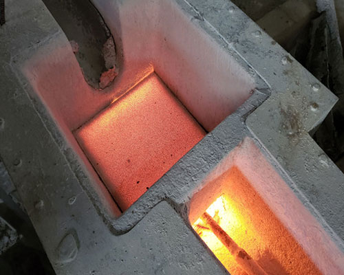
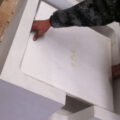
the correct position of ceramic foam filter in the plate filter box
What Is the Correct Step-by-Step Ceramic Foam Filter Placement Method?
Step 1: Inspect the Filter Box Before Placement
Before inserting a new filter, inspect the filter box interior:
- Check the filter seat (refractory ledge) for cracks, erosion, or residual metal and slag buildup from the previous campaign. Any debris on the seat surface will prevent the new filter from sitting flat.
- Remove all residual aluminum, slag, and refractory fragments from both the inlet and outlet chambers. A clean box is a prerequisite for a clean seal.
- Inspect the refractory lining for damage. Cracks or spalling in the lining above the filter seat can allow metal to infiltrate behind the filter and bypass it entirely.
- Verify that the launder connections on the inlet and outlet sides are clear and properly aligned.
This inspection takes 10–15 minutes and prevents the majority of placement-related filtration failures. Skipping it is one of the most common shortcuts that experienced foundry managers learn to forbid.
Step 2: Inspect the Ceramic Foam Filter
Before placing the filter into the box, examine the filter itself:
- Check for cracks, chips, or broken edges. A filter with visible edge damage will not seal properly against the filter seat.
- Verify the filter dimensions match the filter box seat dimensions. The filter should fit the seat with a slight interference — typically 1–2 mm per side — to ensure edge sealing without excessive force during installation.
- Confirm the filter PPI grade matches the specification for the current alloy and casting parameters. Using the wrong PPI grade — too fine or too coarse — is a surprisingly common error, particularly on lines that run multiple alloy grades.
- Check for moisture. Filters that have been stored in humid conditions may have absorbed moisture, which will cause steam generation and potential thermal shock cracking during preheat. Dry filters should feel completely dry to the touch and show no discoloration from moisture exposure.
Step 3: Place the Filter on the Seat
This is the core of the ceramic foam filter placement method, and it needs to be done correctly:
- Lower the filter horizontally into the filter box and seat it flat on the refractory ledge. The filter face should be level — parallel to the melt surface — with no tilt or angular offset.
- Press the filter gently but firmly against the seat on all four sides to confirm full contact. The filter edges should sit flush against the seat surface around the entire perimeter.
- If the filter box design uses a gasket or fiber seal strip between the filter edge and the seat, install this sealing material before placing the filter. The seal strip fills any minor dimensional gaps and prevents metal bypass at the edges. Many plate-type filtering units are designed with a groove in the seat specifically for this seal material.
- Verify visually that the filter is centered in the seat — not shifted toward the inlet or outlet side. An off-center filter will have unequal support and uneven flow distribution.
Step 4: Close the Filter Box and Preheat
After the filter is seated:
- Close the filter box lid carefully, ensuring it does not contact or shift the filter during closure.
- Begin preheating the filter box and the filter to operating temperature. For aluminum casting applications, the target preheat temperature is typically 500–600°C. The preheat should use a controlled ramp rate — usually 80–100°C per hour — to avoid thermal shock cracking of the filter.
- Maintain the preheat temperature for a minimum hold period (typically 30–60 minutes) before introducing molten aluminum. This ensures the filter, the refractory lining, and the seal material are all uniformly heated and ready to receive the melt without localized freezing.
- During preheat, verify that the burner flame pattern is not directed at the filter surface. Direct flame impingement can cause localized overheating and thermal stress damage. The flame should heat the filter box chamber indirectly.
Step 5: Introduce Molten Aluminum
When the preheat is complete and the filter box has reached target temperature:
- Begin transferring molten aluminum into the inlet chamber at a controlled rate. Do not dump a large volume of metal into the inlet side suddenly — this creates a high-pressure spike across the filter that can fracture it on first contact.
- Allow the melt level in the inlet chamber to rise gradually until it covers the filter face by at least 25–30 mm. This ensures the filter begins receiving metal across its full area rather than at a single point.
- Monitor the melt level in both the inlet and outlet chambers during the initial fill. A large level difference between inlet and outlet indicates high flow resistance — which could mean the filter is partially blocked, misaligned, or not fully seated.
- Once stable flow is established through the filter, casting can begin downstream.
What PPI Grade Should Be Used for Different Aluminum Alloys?
The pores-per-inch (PPI) rating of the ceramic foam filter determines the fineness of filtration and the flow resistance. Selecting the right PPI for your alloy grade and casting parameters is part of the overall ceramic foam filter placement method — because PPI selection directly affects how the filter performs in the plate-type filtering unit.
| Alloy Series | Typical Application | Recommended PPI | Reasoning |
|---|---|---|---|
| 1xxx (pure Al) | Foil stock, electrical conductor | 30–50 PPI | Low inclusion load; finer filtration achievable |
| 3xxx (Al-Mn) | Beverage can body stock, building panels | 30–40 PPI | Moderate inclusion load; good balance of flow and filtration |
| 5xxx (Al-Mg) | Automotive sheet, marine plate | 20–30 PPI | Higher Mg reactivity generates more oxide; coarser filter avoids premature clogging |
| 6xxx (Al-Mg-Si) | Structural extrusion billet | 30–40 PPI | Moderate inclusion population; standard filtration adequate |
| 8xxx (Al-Fe) | Thin foil, heat exchanger fin | 40–60 PPI | Demands highest surface quality; fine filtration justified |
PPI recommendations are general guidelines based on AdTech application experience across multiple casting facilities. Actual PPI selection should account for specific melt treatment practice, target inclusion size, and casting speed. Consult your filtration equipment supplier for application-specific guidance.
For most aluminum rolling operations running plate-type filtering units, 30 PPI is the most commonly used grade — it handles the majority of commercial alloy grades at standard casting speeds without excessive flow restriction. Foundries with particularly demanding surface quality requirements — thin foil producers, for instance — typically move to 40 or 50 PPI and accept the slightly higher flow resistance in exchange for finer inclusion removal.
What Are the Most Common Filter Placement Mistakes in Plate-Type Filtering Units?
Based on field experience and technical service records from operating aluminum casting facilities, the following placement errors occur repeatedly. Each one is avoidable through proper training and procedure adherence.
| Error | What Goes Wrong | Result | How to Prevent It |
|---|---|---|---|
| Filter placed off-center on seat | Uneven support; gap on one or more edges | Metal bypass; inclusion contamination | Center filter visually; check all four edges before closing lid |
| No edge seal material used | Direct filter-to-refractory contact with gaps | Bypass flow around filter perimeter | Install fiber gasket or seal strip per manufacturer specification |
| Inadequate preheat temperature | Filter is below 400°C when metal is introduced | Thermal shock cracking; pore blockage from frozen metal | Follow preheat SOP: 500–600°C with 30-minute hold minimum |
| Metal introduced too fast at startup | Pressure spike across filter face | Filter fracture within first minutes of operation | Control initial fill rate; raise inlet level gradually |
| Wrong PPI grade installed | Filter too fine for alloy/casting conditions | Premature clogging; flow restriction; possible filter collapse | Verify PPI against production schedule before placement |
| Filter stored in humid conditions | Moisture content above 1.5% | Steam generation during preheat; thermal shock cracking | Store below 60% RH; check moisture before use |
Error data reflects patterns observed across AdTech’s customer installations in aluminum casting operations. The most frequent single cause of premature filter failure in plate-type units is inadequate preheat — it accounts for roughly one-third of all avoidable filter failures.
How Does Filter Placement Affect Downstream Casting Quality?
The connection between ceramic foam filter placement in the filter box and final strip or billet quality is direct and measurable. When the filter is correctly placed, properly preheated, and appropriately matched to the alloy and casting parameters, the melt that exits the filter box and enters the casting launder system is significantly cleaner than the melt that entered.
Specific quality impacts that trace back to filter placement include:
Surface defect reduction. Oxide inclusions that are not captured by the filter become embedded in the solidified strip surface. These show up as pinholes, streaks, or surface roughness in the finished product. Proper filter placement — ensuring full face coverage, no bypass flow, and correct PPI selection — typically reduces surface inclusion counts by 60–85% compared with unfiltered metal. This translates directly to lower scrap rates and fewer customer quality claims.
Improved mechanical properties. Non-metallic inclusions act as stress concentrators in the solidified aluminum matrix. Castings and strip produced from well-filtered metal show more consistent tensile strength, better elongation, and improved fatigue resistance compared with equivalent products from poorly filtered or unfiltered melt. For structural applications — automotive body sheet, aerospace skin panels — this consistency is a specification requirement, not an option.
Extended downstream equipment life. Clean melt is less aggressive toward downstream components. The caster tip , in particular, benefits significantly from upstream filtration. Oxide particles in the melt accelerate the degradation mechanisms inside the caster tip channel — surface deposition, pore blockage, and subsurface penetration — that ultimately cause tip blockage and line downtime. Better filtration upstream means longer tip life downstream.
More consistent casting operation. Unfiltered or poorly filtered metal introduces variability into the casting process. Inclusion particles that pass through the caster tip can cause localized solidification disruptions, strip breakage, or roll surface damage. Eliminating this variability through effective filtration — starting with correct filter placement — produces a more stable, more predictable casting operation that is easier to schedule and less costly to run.
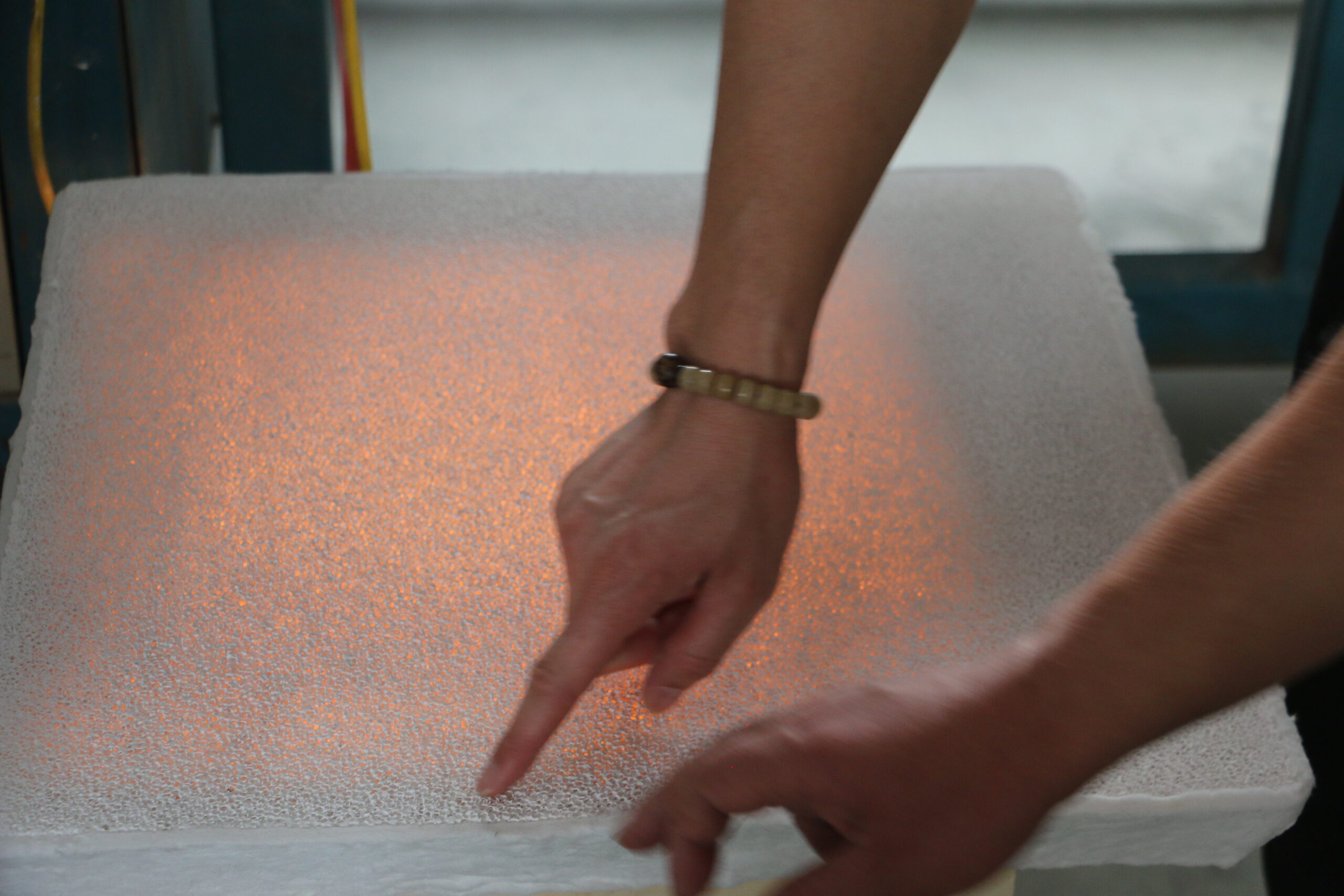
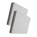
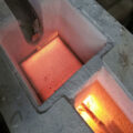
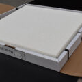
Ceramic foam filter installed in a filtration box during molten aluminum processing, effectively removing inclusions before casting.
How Often Should the Ceramic Foam Filter Be Replaced in a Plate-Type Unit?
Filter replacement frequency depends on several factors:
- Alloy grade — higher-Mg alloys (5xxx series) generate more oxide and load the filter faster
- Melt cleanliness upstream — operations with effective degassing and fluxing treatment deliver cleaner metal to the filter, extending its useful life
- Casting throughput — higher tonnage per campaign means more metal passing through the filter
- PPI grade — finer filters capture more inclusions but clog faster
For most aluminum continuous casting operations, filter replacement occurs at the end of each casting campaign — typically every 8–24 hours of continuous operation, depending on the factors above. Some high-volume operations running very clean melt through 30 PPI filters report filter life of 36–48 hours before replacement is needed.
The practical indicator that a filter is approaching end of life is a rising melt level differential between the inlet and outlet chambers of the filter box. As captured inclusions accumulate in the filter’s pore structure, flow resistance increases and the inlet level rises relative to the outlet. Monitoring this level differential during the casting run provides a reliable, real-time indication of remaining filter capacity.
When the level differential reaches the threshold specified by the equipment manufacturer — typically 30–50 mm depending on filter box design — the filter should be replaced at the next scheduled line stop. Running a fully loaded filter beyond its capacity risks filter collapse under the accumulated pressure load, releasing captured inclusions and filter debris into the melt stream — the worst possible outcome.
Does the Quality of the Plate-Type Filtering Unit Itself Affect Filter Placement?
Absolutely. The filter box and the filter are a system — one cannot perform properly without the other.
A plate-type filtering unit with a warped or eroded filter seat will not support the filter evenly, no matter how carefully the operator places it. A unit with cracked refractory lining will leak metal around the filter. A unit with inadequate insulation will lose heat during the campaign, causing temperature gradients across the filter that reduce its effective area.
This is why equipment quality matters as much as filter quality. AdTech’s plate-type filtering units are designed specifically to support consistent filter placement and performance:
- Precision-machined filter seats with consistent dimensions and flatness across the full seating perimeter
- High-quality refractory lining resistant to aluminum melt erosion and thermal cycling
- Integrated seal groove design that accepts standard fiber gasket material for reliable edge sealing
- Efficient preheat burner geometry that heats the filter and chamber uniformly without direct flame impingement
- Thermal insulation sufficient to maintain melt temperature within ±5°C across the filter during normal operation
When the equipment is engineered to support proper filter placement, the operator’s task becomes simpler and more repeatable — which is exactly the point. The goal is to make correct placement the easy, natural outcome rather than something that requires exceptional skill or attention on every installation.
What Is the Relationship Between Filter Placement and Overall Melt Treatment?
The ceramic foam filter in the plate-type filtering unit is one stage in a complete melt treatment sequence. Its performance — and the demands placed on it — depend directly on what happens upstream.
A typical aluminum melt treatment sequence in a modern casthouse includes:
- Furnace fluxing and skimming — removes bulk dross and large oxide masses from the melt surface
- Inline degassing — removes dissolved hydrogen and floats out small oxide particles through rotor-driven inert gas injection using equipment such as an online degassing unit
- Inline filtration — captures remaining suspended oxide inclusions, typically particles in the 10–100 μm range, using the ceramic foam filter in the plate-type filtering unit
- Final delivery — clean melt passes through the launder system to the caster tip and into the casting machine
Each stage reduces the inclusion burden for the next stage. If furnace fluxing is skipped or done poorly, the degassing unit receives dirtier metal and must work harder. If degassing is inadequate, the ceramic foam filter receives a higher inclusion load and clogs faster. If the filter is placed incorrectly or the wrong PPI is selected, contaminated metal reaches the caster tip and causes downstream problems.
The ceramic foam filter placement method operates within this system context. Optimizing filter placement while neglecting upstream treatment is like installing a high-quality air filter in a car while leaving the engine running with a failed PCV valve — the filter will catch more than it should have to, and its life will be shorter than it needs to be.
Facilities that achieve the best melt cleanliness results — and the lowest total filtration cost per ton — are those that optimize every stage of the treatment sequence together, rather than treating each stage in isolation.
FAQ
1. Why is correct filter placement in the filter box so important?
To prevent unfiltered metal from bypassing the filter, ensure even melt flow across the filter face, and avoid filter fracture during casting.
2. What happens if the filter is placed incorrectly?
It can lead to metal bypassing the filter, causing inclusion defects in the final product, uneven flow, and even premature filter breakage.
3. What is the most common filter placement mistake?
Skipping or rushing the preheating step. This causes thermal shock, which can crack the filter instantly when molten metal is introduced.
4. How can I prevent metal from bypassing the filter?
Ensure the filter seat is clean, use a sealing gasket around the filter edge, and verify the filter is centered and fully seated before closing the lid.
5. Why is preheating the filter and filter box so critical?
It prevents thermal shock. A cold filter can crack when it contacts hot molten aluminum. Proper preheating ensures the filter and box are ready for the melt.
6. Which PPI grade is best for aluminum casting in these units?
It depends on the alloy. 30 PPI is common for general use, while finer grades (40-50 PPI) are for high-purity applications, and coarser grades (20 PPI) for high-Mg alloys.
7. How often should the ceramic foam filter be replaced?
Typically after each casting campaign (e.g., 8-24 hours). Monitor the melt level difference between the inlet and outlet; a large difference means the filter is clogged.
8. What’s the purpose of the fiber gasket or seal around the filter?
It creates a positive seal between the filter edge and the refractory seat, compensating for small gaps and preventing any molten metal from bypassing the filter.
9. Where does the plate-type filtering unit fit in the casting line?
It is installed inline within the launder system, usually placed between the online degassing unit and the casting machine.
10. Can filter placement affect the life of my caster tip?
Yes, definitely. Proper filtration provides cleaner metal to the caster tip, reducing oxide buildup and extending the tip’s service life, which means fewer line stoppages.
Related posts:
 Ceramic Foam Filtering Method
 Ceramic Foam Filter Canada
 How to Choose Ceramic Foam Filter
 Filtration Method
 Best Ceramic Foam Filter
 Foundries Foam Ceramic Filter
 CFF Ceramic Foam Filter
 Ceramic Foam Filter for Aluminium Casting
 Aluminum Foundry Foam Ceramic Filter
 Ceramic Foam Filter Installation
 Alumina Ceramic Foam Filter Installation
 Ceramic Foam Filter Uses
 Ceramic Filter Media for Aluminum
 Filtration Purification Method
 Molten Metal Ceramic Foam Filtration