Foundry ceramic filters are porous refractory components designed to remove non-metallic inclusions, oxide films, and entrained slag from molten metal during casting. A properly specified ceramic filter reduces inclusion content by 50–90%, directly cutting scrap rates, improving mechanical properties, and extending die and tool life downstream. If you’re seeing porosity defects, surface cracks, or parts failing mechanical tests, the filtration stage is almost always the first place worth a hard look.
If your project requires the use of Foundry Ceramic Filters, you can contact us for a free quote.
Why Every Foundry Needs Advanced Ceramic Filtration
Using a high-quality ceramic filter is not just a cost — it’s an investment in yield rate. Unfiltered molten metal contains slag, dross, and oxide films that lead to casting rejection and expensive rework. The inclusion problem is worse than most people outside the foundry realize. Aluminum oxide films form almost instantaneously when molten aluminum contacts air. A typical unfiltered aluminum melt carries oxide bifilms, alkali oxide particles, carbides from crucible contamination, and various intermetallic inclusions — all of which end up in the solidifying casting and act as crack initiation sites, porosity nucleation points, and stress concentrators.
Integrating ceramic filters into your gating system delivers three immediate, measurable benefits:
- Elimination of inclusions: Effectively removes micron-sized impurities through deep-bed filtration, targeting the bifilms and fine oxides that conventional strainers miss entirely
- Turbulence reduction: Converts chaotic, turbulent metal flow into smooth, laminar flow — preventing air entrapment and mold erosion that introduce new defects downstream of the filter
- Increased yield: Reduces inclusion-related scrap by 50–80% in well-documented foundry studies, which translates directly to lower production cost per good part
The economics are straightforward. The cost of a ceramic foam filter is a small fraction of the value of metal saved from a single avoided scrap event. Once you’ve run the numbers, the question shifts from “can we afford filters?” to “why weren’t we using better ones sooner?”
What Are Foundry Ceramic Filters and How Do They Work?
At their core, foundry ceramic filters work by forcing molten metal through a rigid porous matrix — either a foam-like open-cell structure or a series of parallel channels — that physically traps solid inclusions while allowing clean metal to pass through.
How It Works: The Three Filtration Mechanisms
To truly understand why foam filters outperform simpler strainer cores, it helps to know that filtration happens through three distinct physical mechanisms running simultaneously:
Screening (Sieving): Large particles of dross and slag that are physically larger than the filter pores are mechanically blocked at the filter face. This is the most intuitive mechanism — the filter acts as a physical barrier. It handles the coarse stuff, but it’s only the beginning.
Filter Cake Filtration: As large particles accumulate on the filter surface, they form a “filter cake” that progressively traps even finer particles, increasing efficiency over time during a pour. The filter actually gets better at its job as the cast proceeds — up to the point of saturation.
Deep Bed Adsorption: This is the real advantage of ceramic foam filters over extruded strainer cores. Small inclusions that would pass straight through a simple barrier are instead trapped inside the tortuous, winding path of the ceramic foam body. Surface tension and chemical affinity between the ceramic surface and inclusion particles cause them to adhere to the internal pore walls. This mechanism captures fine oxides that no mechanical sieving could stop.
When the adsorbed particles reach saturation — meaning the number of particles being captured equals the number being swept away by flowing metal — the filter’s slag removal capacity drops. At that point, it needs to be replaced with a fresh unit. This is why single-use protocol matters.
Types of Ceramic Filters for Foundry Applications
The material composition of a ceramic filter determines which metals it can handle and at what temperatures. This is where many purchasing mistakes happen — engineers spec the cheapest available filter, and then the filter either dissolves into the melt, cracks under thermal shock, or simply fails to capture the inclusion types causing their defects.
We offer a comprehensive range of filters tailored to specific casting temperatures and alloy types. Choosing the right material is critical for both safety and performance.
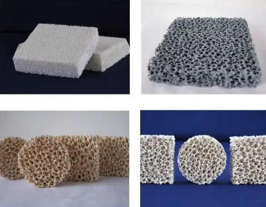
Different types of ceramic filters for foundry: Alumina, SiC, and Zirconia
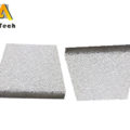
1. Alumina Ceramic Foam Filters (CFF)
Target alloy: Aluminum and aluminum alloys
Temperature limit: Up to 1100°C
Mechanism: Uses an internal 3D reticulated network structure to capture fine oxides in aluminum melts through deep-bed adsorption
Best for: Aluminum billets, slab casting, and precision foundry parts
Alumina foam filters are the most widely used type in aluminum casting and copper alloy foundries. They have excellent non-wetting characteristics against aluminum and are available in the widest range of pore sizes (10 through 60 ppi). Most of the ceramic foam filters used in aluminum rod, billet, and slab casting — including the ceramic foam filter products we supply to continuous casting operations — fall into this category.
2. Silicon Carbide (SiC) Ceramic Foam Filters
Target alloy: Grey iron, ductile iron, copper, and bronze
Temperature limit: Up to 1500°C
Mechanism: High thermal shock resistance allows the filter to withstand aggressive heat from molten iron while filtering out slag and sand inclusions
Best for: Sand casting and iron foundry applications
SiC’s thermal conductivity is higher than alumina, which helps the filter heat up rapidly without cracking when the first metal contacts it — a critical property at iron casting temperatures.
3. Zirconia Ceramic Foam Filters
Target alloy: Carbon steel, stainless steel, and superalloys
Temperature limit: Up to 1700°C
Mechanism: Extreme refractoriness ensures the filter remains structurally sound during the pouring of heavy steel castings where other filter materials would simply fail
Best for: Large-scale steel casting and aerospace components
4. Extruded Ceramic Filters (Honeycomb)
Target alloy: Grey iron and aluminum
Structure: Straight-channel honeycomb design rather than tortuous foam path
Advantage: High mechanical strength and cost-effectiveness for large volume flows where flow rate matters more than fine inclusion removal (PPI is less critical than throughput)
The honeycomb structure means metal takes a direct path rather than winding through foam cells — lower filtration efficiency for fine inclusions, but significantly lower flow resistance. This makes extruded filters the practical choice for high-throughput iron casting where maintaining pour rate is the primary concern.
Technical Specifications and Selection Guide
Engineers should select the correct pore size (PPI — pores per inch) based on casting requirements. Higher PPI means finer filtration but higher flow resistance. Getting this balance wrong costs more than the filter itself.
| Filter Type | Color | Main Component | Max Temp (°C) | Common PPI | Application |
|---|---|---|---|---|---|
| Alumina CFF | White | Al₂O₃ | 1,100°C | 10, 20, 30, 40, 50, 60 | Aluminum foundry |
| SiC CFF | Grey/Black | SiC | 1,500°C | 10, 20, 30 | Iron/copper foundry |
| Zirconia CFF | Yellow | ZrO₂ | 1,700°C | 10, 20, 30 | Steel foundry |
| Extruded (Honeycomb) | White/Brown | Cordierite/Mullite | 1,450°C | 100–300 CPSI | General casting |
Filter classification and temperature ratings aligned with industry standards referenced by The Minerals, Metals & Materials Society (TMS). PPI availability varies by manufacturer and filter dimensions.
Pro tip: For most gravity casting aluminum applications, 30 PPI or 40 PPI is the industry standard balance between flow rate and filtration efficiency. Finer isn’t always better — if your metal temperature is running low or your gating system already has high resistance, stepping from 30 to 40 PPI might give you misruns on thin-walled sections before you get any quality benefit.
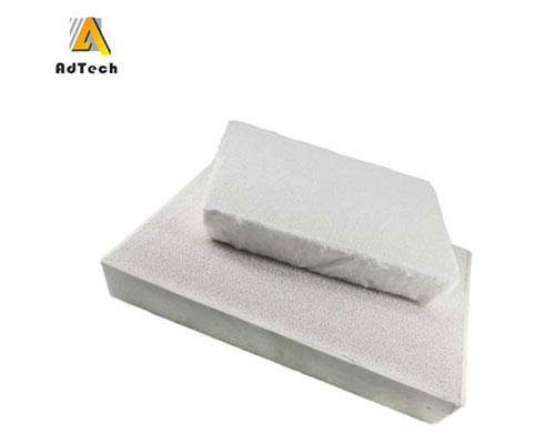
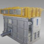
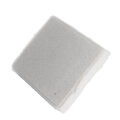
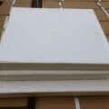
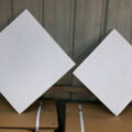
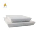
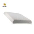
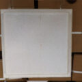
Foundry Ceramic Filters
What Pore Size Ceramic Filter Do You Need?
Pore size is the single most important specification to get right, and the general framework is simpler than it sounds once you know the logic:
- 10 ppi: Coarse filtration, high flow rate. Used for large castings with high metal throughput where only large slag chunks need removal. Common in iron foundries for straightforward structural castings.
- 20 ppi: The standard middle ground for iron and heavy copper alloy casting. Good balance between filtration efficiency and flow resistance.
- 30 ppi: The most common choice for aluminum alloy casting — billet, slab, and shaped casting. Captures oxide films and fine inclusions without choking flow.
- 40 ppi: For tighter inclusion specs — aluminum for automotive structural parts, heat exchanger tubing, aerospace billets.
- 50–60 ppi: Fine filtration for the most demanding aluminum applications. Often used downstream of a 30 ppi filter in two-stage systems rather than as a standalone.
One thing that’s easy to overlook: always calculate filter area and expected flow rate before locking in pore size. Most filter manufacturers including our team can provide flow resistance curves to verify the selection before you commit to a production run.
Foundry Ceramic Filter Requirements: What Separates Good Filters from Bad Ones
Ceramic foam filter quality varies more than the product’s simple appearance suggests. A filter that looks right might have irregular cell structure, density variations, or inadequate high-temperature strength — failures that only show up mid-cast. Here’s what actually matters:
Size accuracy: The size specifications must be accurate. Dimensional tolerance needs to be tight — typically ±1–2 mm — because filter dimensions have to match the filter box for an effective perimeter seal. Wide dimensional variation forces you to compensate with extra gasket material, which is a workaround rather than a solution.
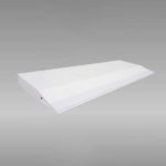
Flatness: Ensure the flatness of the ceramic filter plate. A warped filter creates uneven contact with the filter box seating surface, opening bypass channels at the edges. This is one of the most common and least obvious causes of filtration failure in otherwise well-designed systems.
Accurate porosity: Filters must have accurate, consistent porosity so that filtration accuracy and flow rate can be reliably predicted. Inconsistent pore structure means unpredictable flow behavior — your calculated fill time becomes meaningless if the filter’s actual resistance differs from the rated value.
Sintering strength: A certain sintering strength is the key parameter for measuring whether slag drops — meaning whether the filter sheds particles into the melt rather than retaining them. Inadequate sintering strength is how you end up contaminating the metal with ceramic debris instead of cleaning it.
Surface hardness and coating: The surface hardness of foundry ceramic filters should be high, and special coatings should be applied where required. Surface coatings — boron nitride, colloidal silica — improve chemical resistance and reduce reactivity with specific alloy systems.
Thermal shock resistance — the wash test: The ceramic foam filter plate needs to withstand being contacted by high-temperature molten metal. Because high-temperature aluminum liquid suddenly contacts the filter, the filter must reach close to liquid temperature rapidly without cracking. This means the metal foam filter should have a small linear expansion coefficient. The filter is not allowed to be washed out or softened by the metal flow. Any filter that can’t pass this test will fail in production.
Chemical stability: The chemical stability of the filter must be high — it must not react with aluminum at high temperatures. For alumina filters in aluminum casting, the risk of silica reduction (4Al + 3SiO₂ → 2Al₂O₃ + 3Si) is real if the silica content is too high. High-purity alumina grades minimize this risk.
| Quality Parameter | Minimum Acceptable | Good Quality | Premium Grade | Test Method |
|---|---|---|---|---|
| Compressive Strength (RT) | 0.4 MPa | 0.6–0.8 MPa | >1.0 MPa | ASTM C773 |
| Linear Shrinkage (max temp) | <2% | <1% | <0.5% | ISO 2478 |
| Dimensional Tolerance | ±3 mm | ±2 mm | ±1 mm | Direct measurement |
| Al₂O₃ Purity (alumina filters) | >70% | >85% | >95% | XRF analysis |
| Surface Hardness (Mohs) | 5.5 | 6.5 | >7 | Mohs scratch test |
Quality benchmarks based on standard foundry procurement requirements. Specific values should be defined in purchasing specifications and verified with supplier mill test certificates before first production use.
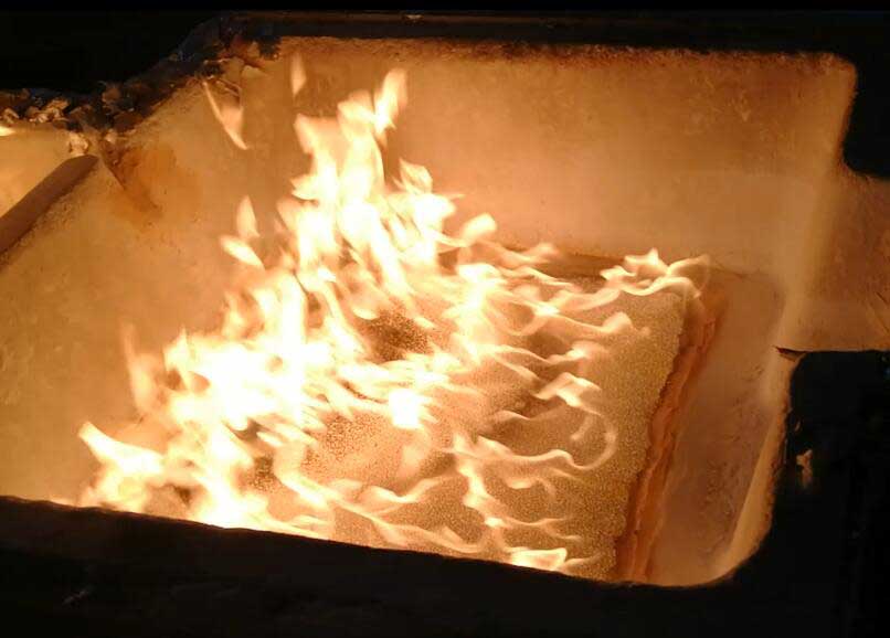
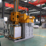
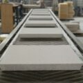
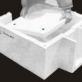
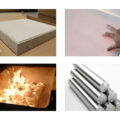
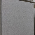
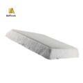
Foundry Ceramic Filter under high-temperature
Installation and Placement in the Gating System
Installation quality determines filter performance as much as the filter specification itself. A perfectly specified filter installed poorly will underperform a mediocre filter installed correctly.
Where to Position the Filter
The principle of the installation position for foundry ceramic filters is to prevent filtered aluminum melt from turning over — meaning re-entraining inclusions — after it passes through the filter. For horizontal flow channels, since the oxide film in the flow channel is continuous, the filter installation location does not need to be very far from the crystallizer. Keeping the filter close to the point of use minimizes the distance over which re-oxidation can occur after filtration.
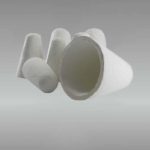
Filter cup / pouring basin: Ideal for direct pouring to prevent turbulence entering the sprue. The filter intercepts metal at the first point of entry before turbulence can develop.
Runner system: The most common placement. The runner cross-section must be expanded at the filter placement area to prevent flow restriction (choking). This is a detail that gets skipped more often than it should — if the runner isn’t widened to compensate for filter resistance, you’ll see fill time increase or, worse, incomplete fill on thin sections.
The goal of proper placement is simple: ensure the metal entering the mold cavity is calm, laminar, and free of oxides. Every turbulent event after the filter is a new opportunity to introduce defects.
Pre-Installation Protocol
Before installing the filter, lightly pat the filter to remove residual ceramic debris, and remove any debris in the flow slot to avoid clogging the foundry ceramic filter prematurely. The combination between the installed filter and the flow slot must not leak — any gap is a bypass path, and a bypass path makes the filter useless. Ceramic fiber paper cut to fit around the filter perimeter creates an effective compressible gasket that accommodates minor dimensional variation between filter and box.
Knowing When to Replace the Filter
When filtering with a ceramic foam filter plate, the filter cake forms progressively as surface deposition builds. The CFF filter in the filter box intercepts both large particles and small particles. When adsorbed particles reach saturation — meaning the number of particles being captured from the melt equals the number being swept away by flowing metal — slag removal capacity decreases. At this point, replace the filter with a new one. Attempting to continue beyond saturation actually risks releasing previously captured inclusions back into the melt.
How Ceramic Filters Measurably Improve Casting Quality
The quantified impact of foundry ceramic filters on casting quality is well-documented through operational data from aluminum smelters and published research via The Minerals, Metals & Materials Society (TMS) and the International Journal of Cast Metals Research:
| Casting Quality Parameter | Unfiltered Melt | 30 PPI Filtered | 50 PPI Filtered | Improvement (30 PPI) |
|---|---|---|---|---|
| PoDFA Inclusion Index (mm²/kg) | 0.45–0.80 | 0.10–0.20 | 0.05–0.12 | ~70–75% reduction |
| Tensile Strength (6061-T6) | 275 MPa avg | 295–310 MPa avg | 305–315 MPa avg | ~8–12% |
| Elongation (6061-T6) | 8–10% | 11–14% | 13–15% | ~35–40% |
| Scrap Rate (inclusion-related) | 4–8% | 1–2% | 0.5–1.5% | ~70% reduction |
| Surface Defect Frequency | High | Low | Very low | Significant |
Data synthesized from operational foundry records and published metallurgical research. Values represent typical ranges across multiple alloys and casting configurations; actual results depend on melt quality, pour temperature, and process parameters.
The elongation improvement deserves particular attention. Oxide bifilms in aluminum create unbonded interfaces within the metal matrix — essentially pre-existing cracks before any load is applied. Filtering removes these bifilms before they’re locked into the casting, and the result is a more homogeneous microstructure that deforms plastically rather than fracturing at bifilm interfaces. This is why filtered aluminum castings routinely pass fatigue and crash tests that unfiltered material fails.
AdTech Real Case: Rebuilding a Copper Alloy Casting Operation in Poland
In early 2023, a mid-sized copper alloy foundry in Wrocław, Poland reached out with a quality problem that had been costing them customers. The plant cast a range of brass and bronze alloys — primarily CuZn37, CuSn8, and CuAl10 — for hydraulic fittings and valve bodies supplied to German and Austrian OEMs.
What was happening: Their rejection rate for porosity and surface inclusion defects was running at 6.8% across all alloys, with CuAl10 (aluminum bronze) hitting 9.2% — nearly double the threshold their key customer had flagged as unacceptable. They’d adjusted pouring temperature and degassing time repeatedly without meaningful improvement. Their existing filtration was a simple extruded cordierite strainer core in the runner system, which had been adequate for their earlier product mix but wasn’t coping with the tighter specs required for hydraulic components.
The diagnosis: Our applications team reviewed their gating system drawings and melt treatment records. The aluminum bronze issue was clear — CuAl10 forms a particularly tenacious alumina skin that strainer cores simply cannot capture effectively. The tortuous-path filtration of ceramic foam filters was the logical step up, but the question was which grade and pore size matched their specific process.
Silicon carbide foam filters were the right fit for their temperature range (copper alloy casting runs 1100–1200°C at the sprue) and provided the chemical resistance needed against aggressive aluminum-bronze chemistry.
What was supplied:
- 2,400 units of SiC ceramic foam filters — 20 PPI in 229 mm and 305 mm square sizes to fit existing filter boxes
- 800 units of 30 PPI SiC filters specifically for the CuAl10 alloy, where tighter inclusion control was the priority
- Custom-cut ceramic fiber paper gaskets to seal the filter box perimeters across all casting stations
- Technical consultation on gating system modifications to accommodate the increased flow resistance of foam versus their previous strainer cores
The gating adjustment was minor — widening the runner cross-section by approximately 15% to compensate for filter resistance and maintain fill time — but skipping it would have caused problems. One plant we’ve worked with made exactly that mistake and ended up with misruns on thin-walled sections. The Polish team followed the recommendations properly from the start.
Results at the 3-month review:
- Overall rejection rate dropped from 6.8% to 1.9%
- CuAl10 rejection rate fell from 9.2% to 2.4%
- Their key German customer lifted the quality warning flag and increased quarterly order volume
- The foundry qualified to quote a new line of dezincification-resistant brass fittings for the UK water fittings market — a product category they’d previously avoided because their quality consistency hadn’t been reliable enough
The relationship evolved into a standing supply arrangement covering quarterly filter orders and annual specification reviews tied to any alloy or product mix changes. The ongoing technical engagement — rather than just fulfilling repeat orders — is what actually keeps casting quality moving in the right direction year over year.
Integrating Ceramic Filters Into Your Complete Casting System
Ceramic foam filters perform best as part of a complete melt treatment and filtration system, not as a standalone fix. The filter can only remove what the melt brings to it. If degassing is inadequate, hydrogen porosity persists regardless of filter quality. If the launder introduces oxides downstream of the filter, those can’t be captured either.
The most effective aluminum casting setups combine:
- Melt treatment — flux addition, grain refinement, and degassing using rotary impeller units or online degassing systems to drive down hydrogen content before filtration
- Primary filtration — 30 PPI ceramic foam filter as the main inclusion barrier, sized to the metal throughput of the specific casting line
- Sealing and thermal management — ceramic fiber paper gaskets around the filter box perimeter; insulated launders to maintain metal temperature from furnace to mold
- Flow control — stopper rods, launder flow control components, and properly expanded runner cross-sections at the filter location to ensure stable, non-turbulent flow
Turbulence is the enemy of filtration. Swirling, splashing metal re-entrains inclusions already captured by the filter and introduces new oxides through air contact. A filter installed in a turbulent flow path will perform well below its rated efficiency — the gating geometry is as important as the filter specification.
If you’re building a new casting line or troubleshooting an existing one, the filter is one component. The system is what determines the result. Our team can review the full setup — from melt treatment through gating and filtration — and not just the filter spec in isolation. That’s where the real improvement comes from.
FAQ
1. What do foundry ceramic filters do?
They remove non-metallic inclusions, oxide films, and slag from molten metal during casting, reducing scrap rates by 50–80% and improving mechanical properties of finished parts.
2. What types of ceramic filters are used in foundries?
Four main types: alumina ceramic foam filters for aluminum, silicon carbide foam filters for iron and copper, zirconia foam filters for steel, and extruded honeycomb filters for high-flow iron casting.
3. What PPI ceramic filter should I use for aluminum casting?
30 PPI is the standard for most aluminum billet and slab casting. Use 40–50 PPI for tighter inclusion specs like automotive or aerospace applications.
4. How do ceramic foam filters differ from strainer cores?
Foam filters use a tortuous 3D path that captures fine inclusions through deep-bed adsorption. Strainer cores only block particles larger than their openings, missing fine oxides entirely.
5. Can ceramic foam filters be reused?
No. They are single-use components. A saturated filter releases trapped inclusions back into the melt, contaminating the next cast.
6. Where should I place the ceramic filter in the gating system?
As close to the mold cavity as practical. The runner cross-section must be expanded at the filter location to prevent flow restriction.
7. What causes a ceramic filter to crack during pouring?
Thermal shock — especially in iron and steel casting. Preheating the filter and selecting materials with high thermal shock resistance (SiC for iron, ZrO₂ for steel) prevents cracking.
8. How do I seal the gap between the filter and filter box?
Use ceramic fiber paper gaskets cut to fit the filter box perimeter. Any gap allows molten metal to bypass the filter, defeating its purpose.
9. Do ceramic filters react with molten aluminum?
High-purity alumina filters (>85% Al₂O₃) show no significant reaction at normal aluminum casting temperatures (680–750°C). Lower-purity filters with high silica content can release silicon into the melt.
10. What size ceramic foam filter do I need?
Match filter face area to your metal throughput. Standard sizes range from 7-inch (178 mm) for small casters to 17-inch (432 mm) for high-capacity continuous casting lines.
Related posts:
 Ceramic Filters for Foundry
 Zirconia Ceramic Foam Filter
 Porous Ceramic Filter for Foundry
 Aluminum Casting Filter
 Foam Ceramic Foundry Filters
 Foam Ceramic Filters
 Ceramic Foam Filters for Casting
 Ceramic Foam Filters
 Ceramic Foam Filters for Metal Filtration
 Ceramic Foam Filter for Foundry
 Ceramic Foundry Filters
 Foundry Alumina Ceramic Filters
 Asian Foundry Filters
 Ceramic Foam Filters Foundry
 Foam Filter Material