the structural representation of the aluminum liquid degassing equipment
Description of drawings
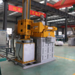
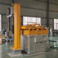
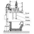
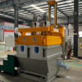
Fig. 1 is the structural representation of an aluminum liquid-degassing machine
In the figure, each representation is respectively: 1-case cover, 2-casing, 3-cavity, 4-import interface launder, 5-exit interface launder, 6-underflow plate, 7-plug, 8 -plug holder, 9-degassing device, 10-heating device.
detailed description
Embodiment Below in conjunction with accompanying drawing, the utility model is described in detail, and the description of this part is only exemplary and explanatory, and should not have any limiting effect on the protection scope of the present utility model. In addition, those skilled in the art can make corresponding combinations of features in the embodiments in this document and in different embodiments according to the description in this document.
An embodiment of the utility model is as follows, referring to Fig. 1.
Fig. 1 is a kind of aluminum liquid degassing equipment, comprising an aluminum liquid degassing box, degassing machine, and heating device. The liquid aluminum rotary degassing includes a box body 2 and a box cover 1; the box body 2 includes a box wall and a hollow cavity 3 arranged in the box wall, and the opening of cavity 3 is upward, including a bottom wall and an inner wall; on one side of the cavity 3 The upper part of the inner wall of the chamber is provided with a liquid inlet docked with the outlet of the launder; the bottom of the inner wall on the other side of the chamber is provided with a liquid outlet docked with other equipment; an underflow plate 6 is installed on the inner wall at one end of the chamber liquid inlet, and The cavity is separated from the outside world. The liquid inlet includes an inlet interface launder 4, and the liquid outlet includes an outlet interface launder 5, a plug 7, and a plug holder 8. Underflow plate 6 is provided with an inclination, and the included angle with the cavity inner wall of its installation place is between 20-70 °, and the lowest point of underflow plate 6 is lower than the lowest point of the liquid inlet. The lowest point of the outlet interface chute 5 is lower than the lowest point of the bottom wall, and the straight line formed by the center points of the bottom surface is tangent to the lowest point of the curved surface structure of the bottom wall, and the section of the outlet interface chute 5 is connected from the end of the bottom wall It gradually becomes larger toward the externally connected end. Plug 7 includes a plug cone and an operating rod, and is used to control the flow rate of the aluminum liquid at the liquid outlet of the aluminum liquid degassing box. A plug cap is sheathed on the described plug cone, and the plug cap is made of refractory material. The blocking cone is conical, and the size is the same as the inner hole of the outlet interface launder. The clamping position is equipped with the operating rod, and the clamping position can make the plug be fixed on the plug holder. Plug frame 8 is installed on the casing. Degassing device 9 and heating device 10 are all installed on case cover 1 of the aluminum liquid degassing machine.
The above is only the preferred embodiment of the utility model, it should be pointed out that for those of ordinary skill in the art, without departing from the premise of the utility model principle, some improvements and modifications can also be made, These improvements and retouching should also be regarded as protection scope of the present utility model.

degassing equipment
Related posts:
 A liquid aluminum degassing box and aluminum liquid degassing unit
The aluminum liquid rotary degasser is an online device for aluminum
What are the characteristics of a liquid aluminum rotary degassing
A liquid aluminum degassing box and aluminum liquid degassing unit
The aluminum liquid rotary degasser is an online device for aluminum
What are the characteristics of a liquid aluminum rotary degassing
 Liquid Aluminum Degassing Equipment
 Aluminum Liquid Degassing Equipment
 Degassing Box for Molten Metal
 Molten Alu Degassing Equipment
 Box Type Degassing Equipment
 Rotary Degassing Purification Equipment
 Degassing Equipment for Aluminum
 Aluminum Liquid Purification Equipment
 Liquid Aluminium Degassing Equipment
 Online Aluminum Liquid Purification Device
 Roll Caster Feed Tip
 Rotating Degassing Equipment