Flux degassing is a melt treatment process used in aluminum casting to remove dissolved hydrogen and non-metallic inclusions from molten aluminum alloys. It works by combining chemical fluxing with inert gas purging: a specially formulated flux powder — typically composed of salts containing chlorine and fluorine — is injected into the melt alongside a carrier gas through a rotating graphite shaft and rotor. The rotating impeller shears the gas into thousands of fine bubbles that scrub through the melt, capturing hydrogen atoms and floating oxide particles to the surface as dross. The result is cleaner, denser aluminum with significantly fewer porosity defects in the final casting.
Most foundries and casthouse operations treat flux degassing as a non-negotiable step before casting. The reason is simple: liquid aluminum actively dissolves hydrogen, which forms by chemical reaction with water vapor:
2Al + 3H₂O → Al₂O₃ + 6H
The solubility of gaseous hydrogen at the melting point of liquid aluminum (1220.7°F / 660.4°C) is 0.61 in³/lb (2.2 cm³ per 100 g). But when aluminum solidifies, that solubility drops dramatically — solid aluminum at the melting point can hold only 0.014 in³/lb (0.05 cm³ per 100 g). This means the aluminum alloy releases excess hydrogen during the solidification process, creating porosity defects distributed throughout the solid metal. The size and number of hydrogen pores depend on the initial hydrogen content, the alloy composition, and the solidification conditions.
A well-executed flux degassing cycle can bring hydrogen from an initial level of 0.30–0.40 mL/100g down to below 0.10 mL/100g in 10–15 minutes of treatment — well within the threshold for most aerospace and automotive specifications.
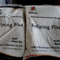
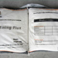
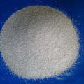
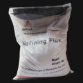
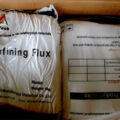
Refining Flux
If your project requires the use of Refining Flux, you can contact us for a free quote.
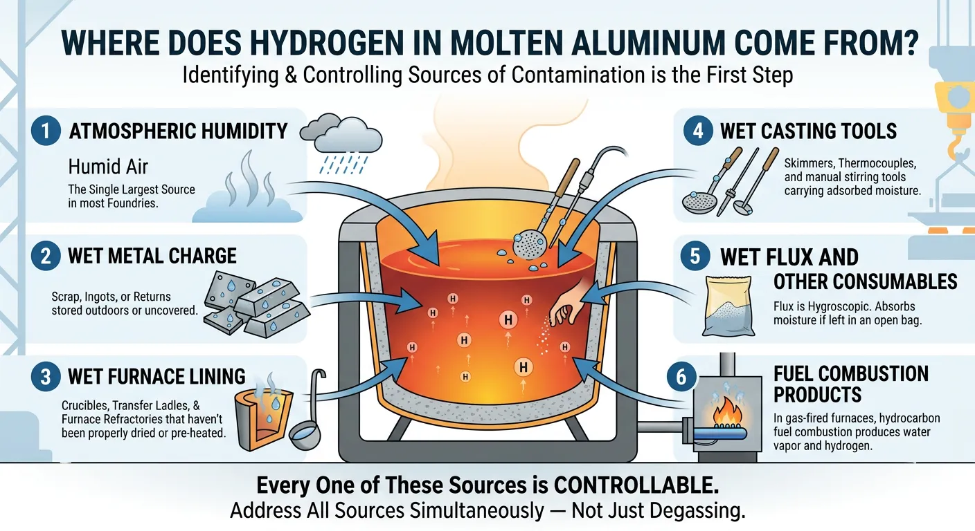
Where Does Hydrogen in Molten Aluminum Come From?
Understanding the sources of hydrogen contamination is the first step toward controlling it. You can’t fix what you haven’t identified. Here are the primary culprits that introduce hydrogen into liquid aluminum:
- Atmospheric humidity — The single largest source in most foundries. Humid ambient air reacts with the melt surface continuously.
- Wet metal charge — Scrap, ingots, or returns stored outdoors or in uncovered areas pick up surface moisture.
- Wet furnace lining — Crucibles, transfer ladles, and furnace refractories that haven’t been properly dried or pre-heated release moisture into the melt on contact.
- Wet casting tools — Skimmers, thermocouples, and manual stirring tools that contact the melt can carry adsorbed moisture.
- Wet flux and other consumables — Flux is hygroscopic. If it’s been sitting in an open bag on the foundry floor, it has absorbed moisture — which means you’re injecting the very thing you’re trying to remove.
- Fuel combustion products — In gas-fired furnaces, the combustion of hydrocarbon fuels produces water vapor (and hydrogen), which can dissolve into the melt through the furnace atmosphere.
Every one of these sources is controllable. Foundries that take hydrogen contamination seriously address all of them simultaneously — not just the degassing step itself.
where does hydrogen in molten aluminum come from
How Does Flux Degassing Actually Work?
The mechanics behind flux degassing are straightforward, but getting the parameters right takes experience.
The Tablet Method
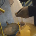
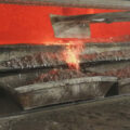
In its simplest form, degassing flux is formed into tablets. When the flux tablets are immersed in the bottom of the furnace using a clean, preheated, perforated bell, the degassing operation starts. The flux components react with the aluminum to form gaseous compounds — primarily aluminum chloride (AlCl₃) and aluminum fluoride (AlF₃). These gas bubbles nucleate and rise through the melt. The partial pressure of hydrogen within the newly formed bubble is very low, so dissolved hydrogen diffuses from the molten aluminum into the bubble according to Sievert’s law. The bubbles escape from the melt surface, carrying hydrogen with them, and the gas is then removed through the exhaust system.
This tablet-based approach works, but it has significant limitations: uneven gas distribution, poor reproducibility between operators, and limited inclusion removal capability.
The Rotary Injection Method
Modern flux degassing takes a more controlled approach. A degassing unit — typically a shaft-and-rotor system — is lowered into the molten aluminum bath held between 680°C and 750°C. The rotor spins at a controlled speed (usually 200–600 RPM), and inert gas is fed down through the hollow shaft. The rotor’s impeller design shears the gas stream into very small, uniformly dispersed bubbles. Smaller bubbles mean more total surface area, which means more efficient hydrogen pickup.
Powdered flux is metered into the gas stream and carried into the melt. These flux particles serve several functions simultaneously:
- They react with and absorb alkali metals (sodium, calcium, lithium) that cause brittleness and hot cracking in certain alloys.
- They agglomerate oxide inclusions, making them easier to float and skim as dross.
- They reduce surface tension at the bubble-melt interface, improving gas-metal contact and hydrogen removal kinetics.
- They decompose at melt temperature, generating localized micro-bubbles within the flux particle itself — creating a dual-bubble mechanism that enhances degassing efficiency beyond what carrier gas alone can achieve.
The combination is what makes rotary flux degassing far more effective than either tablet degassing or manual surface fluxing alone. You get cleaner metal in less time, with better process consistency.
How Is Hydrogen Content Measured in Molten Aluminum?
You can’t manage what you don’t measure. There are several established methods for estimating or quantifying hydrogen content in the melt:
Slow Solidification Method
A small portion of liquid aluminum (about 2 in³ / 33 cm³) is poured into the cavity of a heated refractory brick. The alloy slowly solidifies, and the released hydrogen concentrates in the upper part of the casting in the form of frozen bubbles. The number and size of hydrogen bubbles visible on the sample surface indicate the relative hydrogen concentration. This method is qualitative — useful for quick shop-floor checks but not precise enough for critical applications.
Vacuum (Reduced Pressure) Test — RPT
This is the most widely used quantitative method in production foundries. A sample portion of the aluminum alloy is allowed to solidify in a small crucible under reduced pressure. The hydrogen dissolved in the alloy begins to form a gas phase (bubbles) under the low-pressure conditions. When the first bubble is formed, the pressure and temperature are measured simultaneously. These parameters are used to determine hydrogen content through established digital charts and graphs. The density of the vacuum-solidified sample compared to an atmospheric-solidified sample gives a “density index” that correlates directly to hydrogen content.
Real-Time Analyzers
Instruments like the ALSPEK H or Alscan probe provide continuous hydrogen readings by measuring the equilibrium hydrogen partial pressure at the melt surface through a porous ceramic probe. These are the gold standard for in-line monitoring but represent a higher capital investment.
| Measurement Method | Type | Accuracy | Speed | Typical Use |
|---|---|---|---|---|
| Slow solidification (brick) | Qualitative | Low–moderate | 5–10 min | Quick shop-floor screening |
| Reduced Pressure Test (RPT) | Semi-quantitative | Moderate–high | 8–12 min | Production QC, most foundries |
| Density index calculation | Quantitative | High | 10–15 min | Complement to RPT |
| Real-time analyzer (ALSPEK/Alscan) | Quantitative | Very high | Continuous | High-volume casthouses, aerospace |
Methods described per ASTM E715 and measurement protocols documented in ASM International Handbook, Vol. 15: Casting.
What Gas Should You Use — Nitrogen or Argon?
This question comes up constantly in foundry discussions, and the answer depends on your operation and your budget.
Nitrogen is the most commonly used carrier gas for flux degassing because it’s roughly one-third the cost of argon and works perfectly well for most commercial casting applications. However, nitrogen can form aluminum nitride (AlN) inclusions at higher melt temperatures or with extended treatment times — something to watch for if you’re casting thin-wall aerospace components.
Argon is truly inert and does not react with aluminum at any temperature. It’s the preferred choice when casting high-purity alloys or when you absolutely cannot tolerate any additional inclusion risk. Many automotive OEMs now specify argon-based degassing in their supplier quality requirements.
Chlorine-based gas mixtures were common decades ago but have been largely phased out due to environmental regulations and worker safety concerns. Modern flux formulations have made chlorine gas injection unnecessary for most applications.
| Gas Type | Relative Cost | H₂ Removal Efficiency | Inclusion Risk | Typical Application |
|---|---|---|---|---|
| Nitrogen (N₂) | Low | 85–92% | Possible AlN at high temp | General foundry, die casting |
| Argon (Ar) | High | 90–95% | None | Aerospace, premium automotive |
| N₂/Ar Blend | Medium | 88–94% | Minimal | Semi-permanent mold, extrusion billet |
| N₂ + Flux Powder | Low–Medium | 92–97% | Very low (flux absorbs inclusions) | All-purpose flux degassing |
Data based on published metallurgical literature and operational benchmarks reported by The Aluminum Association and foundry process audits.
What Types of Flux Are Used in Aluminum Degassing?
Not all fluxes are created equal. Choosing the wrong formulation can introduce problems rather than solve them. There are several categories worth understanding:
Cover Flux
Applied to the melt surface to prevent oxidation during holding. It forms a molten blanket that shields liquid aluminum from atmospheric moisture — the primary source of hydrogen pickup. Cover flux typically consists of NaCl-KCl eutectic blends with small additions of fluorides.
Cleaning Flux (Drossing Flux)
Designed specifically to wet and separate oxide skins from the aluminum. This type is especially useful when processing returns and scrap with heavy oxide contamination. It makes dross drier and more metallic-aluminum-lean, improving your metal recovery rate.
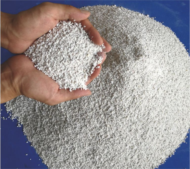
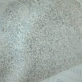
Degassing Flux
Formulated for injection into the melt via a carrier gas, or pressed into tablets for manual immersion. These fluxes contain active chloride and fluoride compounds that react with aluminum at melt temperature to form volatile aluminum chloride and aluminum fluoride. These gaseous reaction products create bubbles with very low hydrogen partial pressure, driving diffusion of dissolved hydrogen out of the melt. Modern injection-grade degassing fluxes are replacing the older tablet form in most production environments because of superior process control.
Grain Refining Flux
Contains titanium and boron compounds that promote fine equiaxed grain structure. Some advanced flux formulations combine degassing and grain refining functions into a single product, saving processing time.
| Flux Type | Primary Function | Key Ingredients | Injection Method |
|---|---|---|---|
| Cover Flux | Oxidation prevention | NaCl, KCl, CaF₂ | Surface application |
| Cleaning Flux | Oxide/dross separation | KCl, NaF, Na₃AlF₆ | Surface or plunging |
| Degassing Flux | H₂ removal + inclusion capture | Chloride-fluoride blends, reactive salts | Gas-injection (rotor) or tablets |
| Grain Refining Flux | Microstructure control | K₂TiF₆, KBF₄ | Plunging or injection |
Composition ranges referenced from ASM International Handbook, Vol. 15: Casting, and industry-standard flux supplier technical data sheets.
How to Optimize Your Flux Degassing Process
Getting good results isn’t just about having the right equipment — it’s about dialing in the parameters for your specific alloy, furnace size, and production rate. Here are the variables that matter most, drawn from years of production experience:
Rotor Speed and Gas Flow Rate
Too fast a rotor speed creates vortexing, which pulls surface oxides back into the melt and defeats the purpose entirely. Too slow, and the bubbles are large and inefficient. For most applications, 300–450 RPM with a gas flow of 5–15 L/min strikes the right balance. You want to see gentle surface movement — not a whirlpool.
Treatment Time
Longer isn’t always better. After about 12–15 minutes, you hit diminishing returns on hydrogen removal and start losing temperature, which wastes energy and can push you outside optimal casting temperature windows. Most production operations target 8–12 minutes per heat.
Flux Addition Rate
Over-fluxing generates excessive fumes, wastes material, and can leave residual salt inclusions in the metal. Under-fluxing doesn’t capture enough non-metallic inclusions. A typical dosage is 0.1–0.3% of the melt weight. Start at the lower end and increase only if your RPT samples or inclusion monitoring data tell you to.
Rotor and Shaft Condition
A worn rotor doesn’t disperse gas properly. Inspect your graphite rotor and shaft assembly regularly — surface erosion and cracks compromise bubble dispersion and can introduce carbon particles into the melt. Replacing a worn rotor is far cheaper than scrapping a batch of castings.
| Parameter | Recommended Range | Effect of Too Low | Effect of Too High |
|---|---|---|---|
| Rotor speed | 300–450 RPM | Large bubbles, poor H₂ removal | Vortexing, oxide entrainment |
| Gas flow rate | 5–15 L/min | Insufficient bubble density | Melt surface disruption, splashing |
| Treatment time | 8–15 min | Incomplete degassing | Temperature loss, wasted energy |
| Flux dosage | 0.1–0.3% of melt weight | Inadequate inclusion removal | Excess fumes, salt contamination |
Process windows based on operational data from aluminum casthouse best-practice guidelines and The Aluminum Association technical resources.
How Does Flux Degassing Compare to On-Line Degassing?
This is a practical question that most foundry engineers and casthouse managers face at some point. Both methods serve the same basic purpose — removing hydrogen and inclusions — but they differ in scale, cost, and where they fit into the process flow.
Flux degassing (ladle or furnace-based) is typically performed in the melting or holding furnace, or in a transfer ladle. It’s a batch process. You treat a specific volume of metal, skim the dross, and pour. This approach is well-suited to foundries with multiple alloys and smaller batch sizes, where flexibility matters more than throughput.
In-line degassing uses a dedicated chamber positioned between the furnace and the casting machine. Metal flows continuously through the degassing unit, where rotors and gas injection treat the metal in real time. This is the standard approach in high-volume operations like DC casting for extrusion billets or rolling slabs.
Many operations actually use both. In-line degassing handles the bulk of hydrogen removal, and an upstream flux treatment in the furnace takes care of alkali metal contamination and heavy oxide loads that would otherwise overwhelm the on-line system’s ceramic foam filter stages.
The key point: flux degassing and in-line degassing are complementary, not competing technologies. If you’re running a high-quality operation, you likely need elements of both.
What Hydrogen Level Is Acceptable for Different Applications?
The target hydrogen level depends entirely on your end application and customer specifications:
- Decorative die castings: < 0.20 mL/100g is generally acceptable.
- Structural automotive castings: < 0.15 mL/100g is the norm.
- Aerospace castings (per AMS 2771): < 0.10 mL/100g, verified by reduced pressure test density measurement.
Given that the starting hydrogen content in untreated melt often sits between 0.25 and 0.40 mL/100g — and can exceed 0.50 mL/100g on humid days or with wet charge — the magnitude of hydrogen reduction that flux degassing needs to achieve is substantial. This is why getting the process parameters right isn’t optional; it’s the difference between shipping castings and scrapping them.
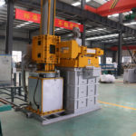
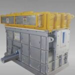
What Equipment Do You Need for Effective Flux Degassing?
A complete flux degassing setup doesn’t require massive capital investment, but each component matters:
Degassing unit: The core of the system. Portable units are popular in job-shop foundries because you can move them between furnaces. Fixed installations with programmable logic controllers offer better repeatability for high-volume production. Look for units that allow independent control of rotor speed, gas flow, and flux feed rate.
Graphite rotor and shaft: The consumable that does the actual work. Rotor geometry — the number, angle, and depth of the impeller vanes — directly affects bubble size distribution. High-purity, oxidation-resistant graphite lasts longer and produces fewer carbon inclusions. A quality rotor should last 60–100 heats before needing replacement, though this varies with melt temperature and alloy chemistry.
Flux feeder: A metering device that introduces powdered flux into the gas line at a controlled rate. Consistency here is critical — clumps of flux cause localized reactions, fume spikes, and uneven treatment. Vibrating or screw-type feeders with adjustable speed work best.
Gas supply: Cylinders or bulk tank of nitrogen or argon, with a flow meter and pressure regulator. Nothing exotic, but the gas must be dry — moisture in the carrier gas is directly counterproductive.
For operations looking to improve melt quality beyond what flux degassing alone can achieve, combining rotary degassing with a downstream filter box and ceramic filtration system creates a multi-stage treatment train that consistently delivers premium metal quality.
AdTech Real Case: Southeast Asian Die Casting Plant Upgrade
In early 2022, a die casting facility in Vietnam producing automotive transmission housings from A380 alloy was experiencing porosity rejection rates between 12% and 18%. Their existing process relied on manual tablet degassing — immersing hexachloroethane tablets into the furnace with a perforated bell — and surface fluxing with hand-spread cover flux. Hydrogen levels measured by RPT were consistently in the 0.25–0.35 mL/100g range, and X-ray inspection was flagging subsurface gas porosity in roughly one out of every six castings. Their largest customer, a Japanese Tier 1 automotive supplier, had issued a quality improvement notice.
The plant contacted AdTech and, after an initial assessment of their furnace layout and production schedule, purchased three portable rotary degassing units with graphite rotor-shaft assemblies, along with a six-month supply of injection-grade degassing flux and a set of ceramic foam filters (30 PPI and 50 PPI) for their launder system.
A technical team spent a week on-site helping the foundry calibrate their process:
- Rotor speed was set at 380 RPM based on their 500 kg furnace capacity.
- Nitrogen flow was adjusted to 8 L/min with flux injection at 0.15% of melt weight.
- Treatment time was standardized at 10 minutes per heat.
- The ceramic foam filters were installed in a newly configured filter box downstream of the degassing station.
- Flux storage procedures were overhauled — all flux moved to sealed drums in a climate-controlled room.
Within the first month, RPT hydrogen readings dropped to 0.08–0.12 mL/100g consistently. Porosity rejection rates fell from the original 12–18% range to below 3%. The Japanese customer approved the updated process and increased order volume by 30%.
By Q4 2022, the foundry had standardized the rotary degassing equipment across all four production lines and signed a long-term supply agreement for consumables including rotors, flux, and filters. Their reject rate stabilized at 1.5–2.2%, and they estimated annual savings of approximately $180,000 in reduced scrap and rework costs.
refining flux from AdTech
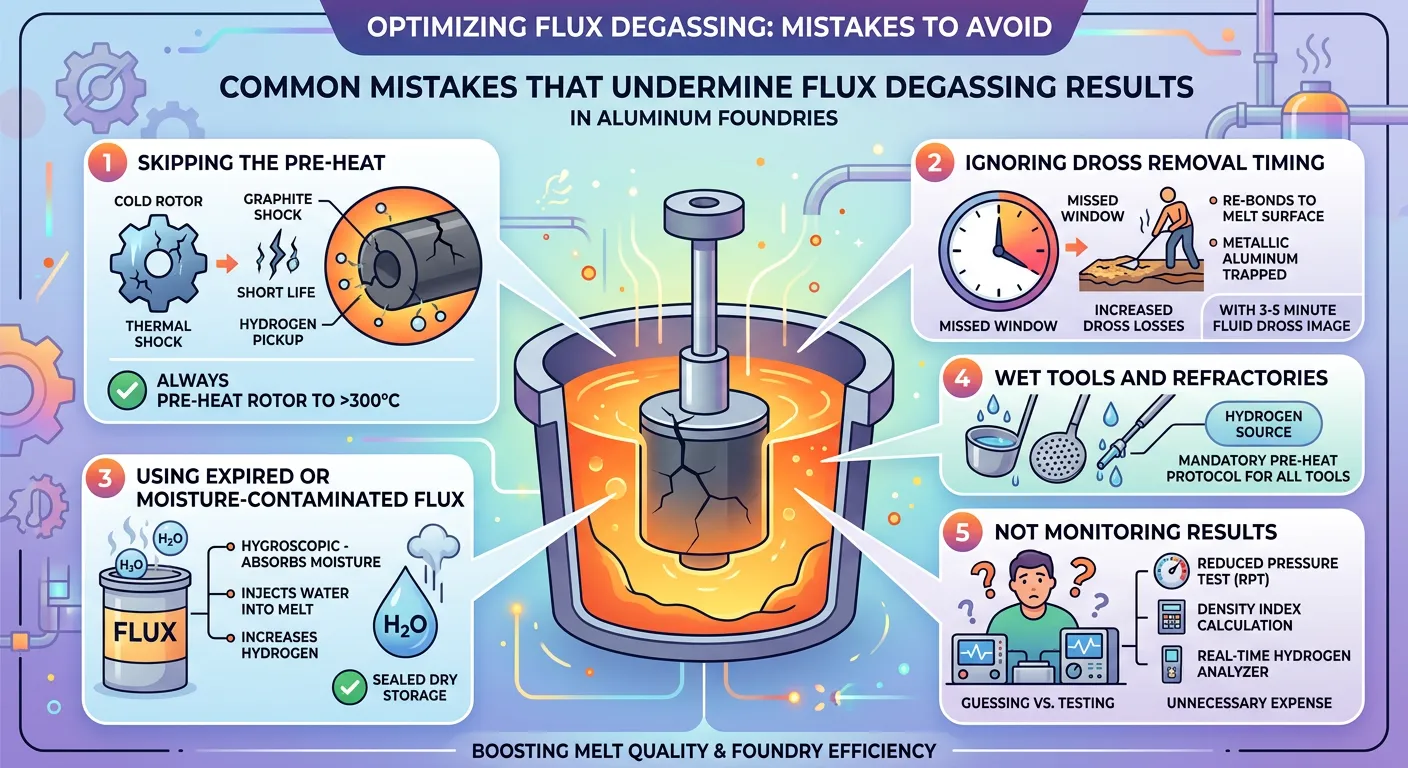
Common Mistakes That Undermine Flux Degassing Results
Even experienced foundries sometimes get tripped up by details that seem minor but have outsized effects on melt quality:
Skipping the pre-heat. Lowering a cold rotor into 720°C aluminum causes thermal shock, which cracks the graphite and shortens its life. It also creates a brief burst of gas from moisture condensed on the shaft surface. Always pre-heat the rotor assembly to at least 300°C before immersion.
Ignoring dross removal timing. After the degassing cycle, there’s a window of about 3–5 minutes where the dross layer is still fluid and easy to skim. Wait too long, and it re-bonds to the melt surface, trapping metallic aluminum and increasing your dross losses.
Using expired or moisture-contaminated flux. Flux is hygroscopic — it absorbs moisture from the air. If it’s been sitting in an open bag on the foundry floor for two weeks, you’re injecting water into a process designed to remove it. Store flux in sealed containers in a dry area, and use it within the manufacturer’s recommended shelf life.
Wet tools and refractories. Every ladle, thermocouple sheath, and skimmer that contacts the melt is a potential hydrogen source. Implement a mandatory pre-heat protocol for all tools, and ensure furnace linings are fully dried after repairs or relining.
Not monitoring results. Reduced pressure testing, density index calculation, or real-time hydrogen analyzers should be part of every shift’s routine. If you’re not testing, you’re guessing — and guessing gets expensive.
Common Mistakes That Undermine Flux Degassing Results
How Does Melt Quality Affect Final Casting Performance?
This isn’t an academic question — it has direct implications for your bottom line and your customer relationships.
Porosity reduces fatigue life. Research published by MDPI’s Metals journal has repeatedly shown that gas porosity and oxide bifilm defects are the dominant factors controlling fatigue crack initiation in cast aluminum components. A casting with 2% porosity can have its fatigue life reduced by 40–60% compared to the same geometry cast from properly degassed metal.
For pressure-tight components — hydraulic valve bodies, EV battery enclosures, fluid manifolds — even micro-porosity that doesn’t show up on standard X-ray can cause leak failures during proof testing. The cost of a single field failure or product recall dwarfs the entire investment in proper melt treatment equipment and consumables.
This is why flux degassing isn’t a “nice to have.” For any operation producing structural, safety-critical, or pressure-containing aluminum castings, it represents the minimum standard for responsible manufacturing.
What Does a Complete Aluminum Melt Treatment System Look Like?
In a well-designed casthouse, flux degassing is one part of an integrated melt treatment chain. Here’s a typical sequence for a high-quality operation:
- Charging and melting — Clean, dry charge materials with minimal returns contamination.
- Furnace fluxing — Cover flux applied to protect the melt surface during holding.
- Rotary flux degassing — In-furnace or ladle-based treatment using a rotor with inert gas and injected flux.
- Dross skimming — Prompt removal of the floated dross layer within the optimal 3–5 minute window.
- Transfer — Controlled pour into a launder system, minimizing turbulence and hydrogen re-absorption.
- In-line filtration — Metal passes through ceramic foam filters to capture remaining inclusions.
- Casting — Clean, degassed, filtered metal enters the mold.
Each step depends on the one before it. Flux degassing cannot fully compensate for dirty charge materials or wet refractories, just as filtration cannot fix a poorly degassed melt. The foundries that consistently produce premium castings are the ones that control every link in this chain.
For operations that want to discuss implementing or upgrading any part of this system — from degassing equipment and graphite consumables to complete filtration solutions — a conversation with an experienced supplier’s technical team is the best starting point. Process conditions vary too much between foundries for one-size-fits-all recommendations to work.
The conclusion of Flux Degassing
Flux degassing remains one of the most cost-effective ways to improve casting quality in aluminum foundries. It addresses the fundamental challenge of aluminum casting: that liquid aluminum dissolves hydrogen readily, and that hydrogen must be removed before solidification or it will manifest as porosity defects throughout your castings.
The science is well established. The equipment is accessible. The process parameters are well documented. What separates good foundries from struggling ones is consistency — in execution, in measurement, and in the discipline to control every source of hydrogen contamination from charge storage to final pour.
If you’re currently using tablet degassing or manual fluxing and wondering whether it’s time to upgrade, the answer is almost certainly yes. The payback period on a rotary flux degassing system is typically measured in weeks, not months, once you factor in the reduction in scrap, rework, and customer quality complaints.
Clean metal makes good castings. There’s no shortcut around that reality, and flux degassing is the most direct path to getting there.
If your project requires the use of Refining Flux, you can contact us for a free quote.
FAQ
1. What is flux degassing in aluminum casting?
Flux degassing is a melt treatment process used to remove dissolved hydrogen and non-metallic inclusions from molten aluminum. It improves metal cleanliness, reduces porosity, and helps produce stronger, more reliable castings.
2. Why is flux degassing important for molten aluminum?
Molten aluminum absorbs hydrogen easily, especially from moisture. During solidification, that hydrogen forms gas pores inside the casting. Flux degassing reduces hydrogen content and lowers the risk of porosity, leaks, and mechanical failure.
3. How does flux degassing remove hydrogen from molten aluminum?
Flux degassing works by introducing flux and inert gas into the melt. Fine gas bubbles attract dissolved hydrogen, which diffuses into the bubbles and rises to the surface. The flux also helps gather inclusions so they can be removed as dross.
4. What causes hydrogen in molten aluminum?
Common hydrogen sources include atmospheric humidity, wet charge materials, damp tools, wet furnace linings, moist flux, and water vapor from furnace combustion products. Even small amounts of moisture can increase hydrogen pickup.
5. What is the difference between flux degassing and rotary degassing?
Flux degassing uses chemical flux to assist hydrogen removal and inclusion cleaning, while rotary degassing uses a spinning rotor to disperse inert gas into fine bubbles. In many plants, the best results come from combining both methods.
6. Which gas is better for aluminum degassing: nitrogen or argon?
Nitrogen is more economical and works well in most foundries. Argon is more inert and is often preferred for high-purity alloys or critical castings where the lowest inclusion risk is required.
7. What hydrogen level is acceptable after flux degassing?
For many aluminum castings, a hydrogen level below 0.15 mL/100 g Al is considered good. For more demanding applications such as aerospace or pressure-tight components, the target is often below 0.10 mL/100 g Al.
8. How do you test hydrogen content in molten aluminum?
The most common methods are the Reduced Pressure Test (RPT), density index testing, and real-time hydrogen analyzers. These methods help foundries confirm whether the degassing process is working effectively.
9. Can flux degassing also remove inclusions?
Yes. In addition to removing hydrogen, flux degassing helps collect oxide films, alkali contaminants, and other non-metallic inclusions. This leads to cleaner melt quality and better casting performance.
10. How long does flux degassing usually take?
In most aluminum foundries, flux degassing takes about 8 to 15 minutes per heat, depending on melt volume, alloy type, gas flow, rotor speed, and the initial hydrogen level in the molten aluminum.
Related posts:
 Refining Flux
 Flux for Aluminum Melt Purification
 Aluminum Refining Flux
 Foundry Flux
 Multi-Function Refining Flux
 Slag Remover
 Aluminum Melt Flux
 Flux Purification for Molten Aluminum
 Aluminium Refining Flux
 Aluminium Refining Agent
 Aluminum Cast Flux
 Aluminum Melting Refining Agent
 Flux for Aluminum Casting
 Molten Metal Refining Flux