What Is a Cartridge Filter and Why Is It Used in Aluminum Filtration?
Cartridge filter is a cylindrical or multi-tube ceramic filtration element used to remove dissolved hydrogen, non-metallic inclusions, and fine impurities from molten aluminum alloy. Unlike flat ceramic foam filters that sit in a gating system and filter metal during pouring, a cartridge filter is typically integrated into an online filtration unit or in-line filtration system that processes the melt continuously as it moves from the holding furnace to the casting station.
The operating principle is different from foam filtration. In a cartridge filter system, molten aluminum passes through or around the ceramic filter elements, which are made from highly porous ceramic materials — typically based on alumina, silicon carbide, or a combination — that provide extremely fine filtration of both solid particles and, in some configurations, assist in degassing through controlled rotor-gas interaction.
Cartridge filtration is particularly common in:
- Continuous casting of aluminum rod and wire (especially electrical conductor grade)
- Billet and slab casting where metal cleanliness specifications are tight
- Wheel and automotive component casting with high mechanical performance requirements
- Foil stock and can body sheet rolling, where surface defects from inclusions are unacceptable
The reason cartridge filters are valued in these applications is not just filtration efficiency. It is the ability to filter large volumes of metal continuously and consistently, without interrupting the casting line to change filter elements as frequently as would be required with flat foam filters.
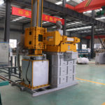
Cartridge filter
How Does the Cartridge Filtration Principle Actually Work?
Understanding the filtration mechanism helps explain why preparation matters so much.
The molten aluminum entering the cartridge filter equipment contains various non-metallic impurities — oxides, spinels, refractory debris, flux residues, and other contaminants ranging from several hundred microns down to single-digit micron sizes. The cartridge filter removes these through a two-stage filtration process:
Surface filtration — Large particles and coarse impurity clusters are intercepted by the outer surface media of the filter tube. As the metal flows toward the tube wall, particles that are larger than the surface pore openings are physically trapped on the external face. Over time, a filter cake of trapped inclusions builds up on this surface, which actually enhances surface filtration efficiency — though it also gradually increases flow resistance.
Depth filtration and adsorption — Smaller particles that pass through the surface layer enter the porous media inside the filter tube wall. As these fine inclusions travel through the tortuous internal pore network, they contact the internal ceramic surfaces and are adsorbed through a combination of Van der Waals forces, surface tension effects, and mechanical entrapment at pore junctions.
Through this double filtering effect of the filter tube, the cartridge filter achieves significantly higher filtration efficiency than single-layer or surface-only filtration methods. The result is high-quality molten metal that meets the cleanliness requirements for demanding production applications — conductor rod, aerospace billet, automotive wheel, and precision die casting.
This dual mechanism is also why cartridge filter preparation is so critical. If the ceramic media is compromised — by thermal shock cracking, moisture contamination, or poor sealing — the internal filtration layer is bypassed or damaged, and the system loses precisely the fine-particle capture capability that justifies using a cartridge filter in the first place.
What Are the Most Common Types of Cartridge Filters for Aluminum?
Before going into preparation and use, it helps to understand the product landscape, because “cartridge filter” covers several distinct configurations that are used differently in practice.
| Filter Type | Structure | Operating Mode | Filtration Target | Typical Application |
|---|---|---|---|---|
| Single-tube ceramic cartridge | Single hollow ceramic cylinder | Outside-in or inside-out flow | Inclusions ≥10 μm | Small-scale inline filtration, lab casting |
| Multi-tube cartridge filter | Multiple parallel ceramic tubes in a housing | Outside-in flow through tube walls | Inclusions ≥5–15 μm | Continuous rod and wire casting |
| Candle filter | Vertical ceramic tube, closed at one end | Outside-in filtration, gravity-assisted | Fine inclusions, some gas | High-purity aluminum, specialty alloys |
| Rigid media cartridge | Bonded ceramic granule block | Depth filtration | Inclusions ≥10–30 μm | High-throughput billet and slab lines |
| Combined degassing-filtration unit | Rotor degassing with downstream cartridge | Gas removal + depth filtration | H₂ + inclusions | Integrated inline treatment systems |
Classification based on industry-standard cartridge filter configurations used in primary and secondary aluminum production. Terminology may vary between equipment manufacturers.
Most foundries and casting plants in the aluminum industry encounter the multi-tube cartridge filter most frequently. It is the workhorse configuration for continuous casting applications and the format most commonly discussed when people ask about cartridge filter preparation before use.
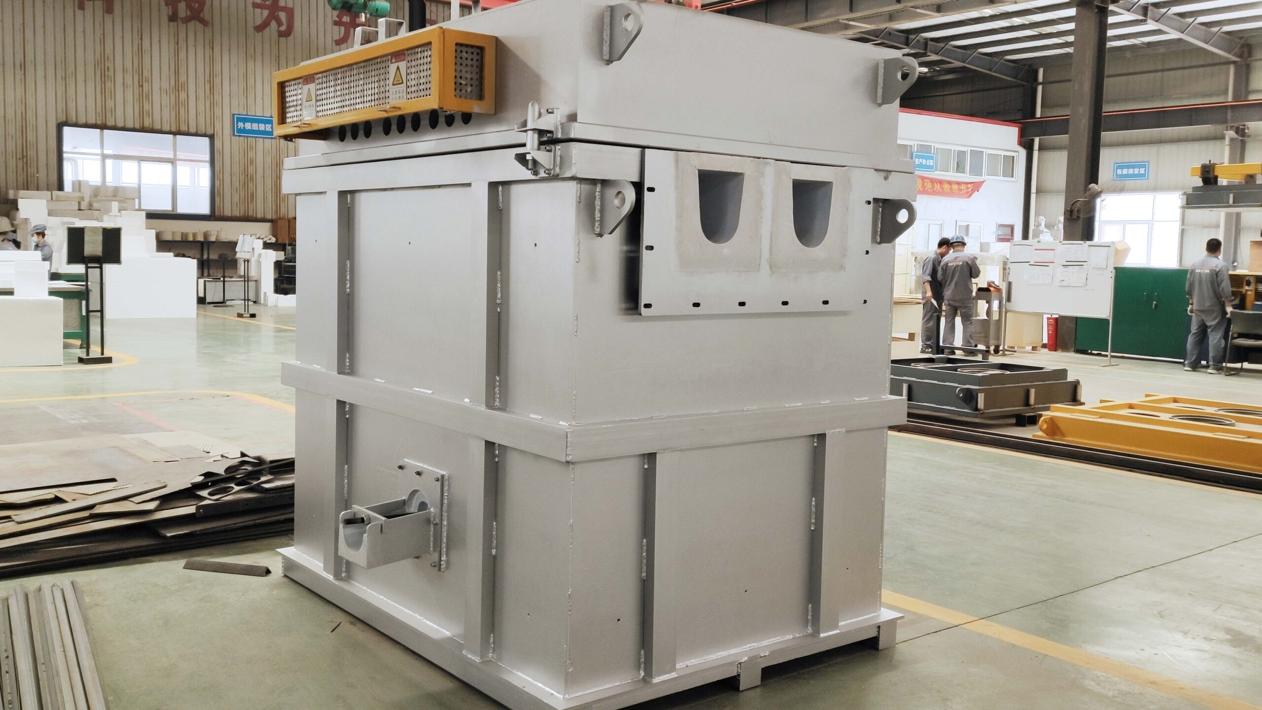
What Are the Main Components of a Cartridge Filter System?
A cartridge filter system is more than just the filter element. Understanding the complete equipment composition helps explain why preparation involves checking the entire assembly, not just the tubes.
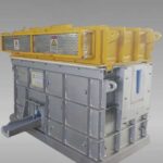
A typical cartridge filter unit includes the following main components:
- Intermediate electrical box — Houses the electrical control and power supply for the heating elements and temperature regulation system
- Heating component — Resistance heating elements installed in the filter box body that maintain the operating temperature during standby and production
- Box cover — The upper lid of the filter housing, which seals the system and includes thermocouple access ports and vent openings
- Box body — The main refractory-lined housing that contains the filter elements and molten aluminum during operation
- Pipe group and lifting fixture — The filter tube assembly and the mechanical fixture used to install, remove, and lift the tube group for inspection and replacement
- Wedge block — Mechanical locking components that secure the filter tube assembly in position within the housing and ensure proper sealing against the refractory lining
Each of these components must be in correct working condition before the system is brought to operating temperature. A malfunctioning heater, a damaged box seal, or a poorly seated wedge block can all lead to filter failure or metal bypass, which is why the pre-operation preparation procedure covers the complete system, not just the ceramic elements
What Preparation Is Required Before a Cartridge Filter Can Be Used?
This is the section that most buyers need and most suppliers gloss over. Getting the preparation right is the difference between a cartridge filter that performs for its full service life and one that fails on the first cast.
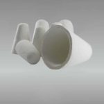
Step 1: Install the tap-out cone and secure the sealing system
Before any heating begins, install the tap-out cone onto the conical plug connector and secure it firmly. Place the assembly into the refractory material lining of the box body, then lower the locking arm into position. Tighten the provided locking bolts to compress the ceramic fiber cone until a liquid-metal-tight seal is achieved.
This step is non-negotiable. If the tap-out cone seal is not metal-tight, molten aluminum will leak during operation, creating a safety hazard and contaminating the area below the filter box. The compressed ceramic fiber cone must be inspected before each campaign — if it shows any signs of erosion, cracking, or deformation from previous use, replace it.
Step 2: Verify all operating parameters
Before proceeding to baking, check whether the parameter settings on the operation interface are correct. This includes:
- Temperature setpoints for baking and operating modes
- Heating element power settings
- Thermocouple assignments and readings
- Alarm and safety interlock settings
It sounds routine, but parameter errors after maintenance or control system updates are more common than anyone likes to admit. A wrong setpoint can lead to under-baking, over-temperature excursions, or failure to reach proper operating conditions.
Why Is Equipment Baking So Important for Cartridge Filters?
The baking procedure is arguably the most critical preparation step, and skipping it or rushing it is the single most common cause of cartridge filter startup problems.
What is the purpose of baking?
Baking serves two essential functions:
- Eliminate adsorbed water from the insulation layer and the fixed lining castables inside the filter box. Water trapped in refractories and insulation will generate steam and potentially hydrogen gas when molten metal enters the box. This moisture must be driven off completely before operation.
- Reduce thermal stress in the lining materials by bringing the entire assembly to operating temperature gradually. Rapid heating creates thermal gradients that can crack refractories, damage insulation, and stress the ceramic filter elements beyond their thermal shock tolerance.
What is the correct baking procedure?
The baking procedure for a cartridge filter system requires careful attention to detail. Here is the complete process, step by step:
a. Prepare the box interior
Place a small amount of carbon at the bottom of the box body. The carbon layer height should not exceed 50 mm. Close the upper cover of the filter box. Use insulation cotton to densely block both the inlet and outlet of the filter box. This creates a semi-sealed environment that allows controlled moisture escape while maintaining thermal uniformity during the baking process.
b. Open the vent nuts before baking
Before starting the baking cycle, twist off the vent nuts located around the box body. These vents allow moisture from the insulation lining to escape as steam during the early stages of heating. If these vents remain closed, trapped steam creates pressure inside the insulation layer, which can cause lining damage or even explosive spalling of castable refractory.
c. Seal the box cover and openings properly
Cover the upper opening of the box with a 20 mm thick fiber blanket and ensure the box cover is well sealed. The aluminum inlet and outlet of the box should be sealed with fiber blanket material, but leave a moisture discharge hole of appropriate size during the heating phase up to 400°C. This allows remaining moisture to escape during the critical dehydration phase. After the temperature exceeds 400°C, plug the moisture discharge holes tightly — by this point, free and chemically bound water should have been driven off, and a sealed environment is needed to maintain temperature uniformity for the remainder of the baking cycle.
d. Install thermocouples for temperature monitoring
Insert a thermocouple into the temperature measuring hole in the box cover and extend it down to the middle and lower part of the cavity to control the furnace gas temperature accurately. For best practice, place an additional thermocouple in the drain hole and connect it to a digital thermometer. This arrangement allows you to monitor the temperature difference between the upper and lower zones of the furnace cavity. A large temperature differential indicates uneven heating, which increases the risk of thermal stress damage to the lining and filter elements.
e. Understand the temperature relationship
The normal process temperature for molten aluminum in the box is approximately 750°C. The furnace gas conduction temperature difference is approximately 50°C above the metal temperature, which means the maximum control temperature of furnace gas during baking is 800°C. Do not exceed this temperature — higher temperatures risk damaging the lining materials and the ceramic filter elements.
f. Use program control if available
If the temperature control meter is equipped with a program control function, set the baking curve according to the manufacturer’s recommended profile and allow it to run automatically. Manual override should remain available in case of anomalies. If the temperature control meter does not have program control, use time-stepped manual control to follow the baking curve. In manual mode, ensure that the maximum current does not exceed the rated current of the heating elements at any power regulator setting.
The following table provides a recommended baking curve for cartridge filter equipment:
| Phase | Temperature Range (°C) | Ramp Rate | Hold Time | Key Action |
|---|---|---|---|---|
| Phase 1 — Initial drying | Ambient → 200 | ≤50°C/hr | 2–3 hours at 200°C | Vent nuts open; moisture discharge holes open |
| Phase 2 — Dehydration | 200 → 400 | ≤50°C/hr | 3–4 hours at 400°C | Chemically bound water release; plug moisture holes after 400°C |
| Phase 3 — Intermediate heating | 400 → 600 | ≤80°C/hr | 2–3 hours at 600°C | Monitor upper/lower temperature differential |
| Phase 4 — Final baking | 600 → 800 | ≤100°C/hr | 4–6 hours at 800°C | Full thermal stabilisation; lining stress relief |
Baking profile based on standard refractory dry-out procedures for aluminum filtration equipment. Actual curve may be adjusted by equipment manufacturer based on lining composition and box dimensions.
g. After baking is complete
Once the hold at 800°C is finished, the system can proceed directly to aluminum production. If the system will not be put into production immediately, the temperature must be lowered to 100°C before opening the lid for inspection. Opening the lid at higher temperatures exposes the hot lining to ambient air, creating rapid thermal gradients that risk cracking the refractory lining. Alternatively, if inspection is not needed, do not open the lid until the system reaches room temperature.
Critical rule: never open the lid partway through the baking cycle or during cooling above 100°C. Partial lid opening introduces cold air that creates localised thermal shock on the lining surface, which can cause spalling and cracking that is expensive to repair and may not be visible until the system is in operation.
What Else Should You Check Before Starting a Cartridge Filter System?
Beyond baking, several other preparation steps determine whether the system will perform correctly.
Is the filter housing properly sealed?
Check all gasket and seal surfaces before installation. Sealing between the filter element and the housing is critical — any gap allows unfiltered metal to bypass the filter entirely. Ceramic fibre gaskets or compression-fit refractory seals should be inspected for damage, replaced if worn, and confirmed to be the correct specification for the filter element diameter and housing geometry.
Is the flow direction correct?
Cartridge filters are directional. Outside-in flow configurations are more common, but inside-out configurations exist for specific applications. Installing the filter in the wrong orientation reduces filtration efficiency and can cause premature clogging. Check the manufacturer’s marking or documentation before installation.
Has the filter been inspected for shipping damage?
Ceramic cartridge filter elements are fragile before installation. Transit damage — micro-cracks, chipped ends, cracked walls — may not be visible to the naked eye but will cause failure under thermal and mechanical stress during operation. Before installation, inspect each element under good lighting for visible cracks, and tap the element lightly to check for the clear ring of an undamaged ceramic versus the dull thud of a cracked one.
Is the upstream melt condition appropriate?
A cartridge filter works most effectively when the melt has already been degassed and roughly treated. Feeding heavily contaminated, high-hydrogen metal directly into a cartridge filter without upstream treatment shortens filter life dramatically and risks rapid clogging.
This is one of the reasons many continuous casting operations run an online degassing unit upstream of the cartridge filter. The degassing unit reduces hydrogen content and floats some inclusions before the metal reaches the filter, which extends filter service life significantly and improves overall melt cleanliness at the casting point.
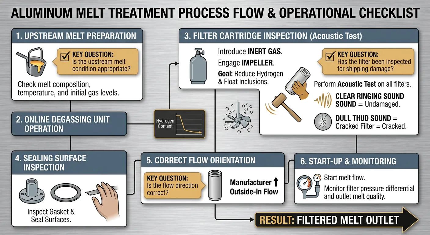
Things you should check before starting a cartridge filter system
How Do You Select the Right Cartridge Filter Specification for Your Process?
Specification selection for a ceramic cartridge filter involves matching several variables to your specific casting operation.
| Selection Parameter | Options / Range | Selection Criteria | Impact of Wrong Selection |
|---|---|---|---|
| Filtration rating (μm) | 5–50 μm typical range | Target inclusion size, alloy grade | Too fine: clogging; too coarse: inclusions pass through |
| Flow rate capacity | Match to casting throughput (kg/min or t/hr) | Casting line speed, metal head | Undersized: flow restriction; oversized: poor residence time |
| Element diameter / length | Varies by manufacturer and housing | Existing housing dimensions or new system design | Poor fit: bypass leakage or installation failure |
| Ceramic material | Alumina, SiC, mixed oxide | Alloy compatibility, operating temperature | Wrong material: chemical attack, contamination |
| Number of elements | Single to multi-tube arrays | Required flow capacity and filtration area | Too few: short service life; too many: unnecessary cost |
| Operating pressure | Typically 0.05–0.3 bar | System design, metal head available | Exceeded limits: filter failure |
Selection guidance based on application engineering principles for ceramic cartridge filtration in aluminum alloy processing. Consult manufacturer specifications for exact sizing.
What flow rate should a cartridge filter handle for aluminum rod casting?
For a standard 8 mm aluminum rod continuous casting line producing around 3–5 tonnes per hour, a properly sized multi-tube cartridge filter system should process the full melt flow without significant pressure drop during normal operation. The filter should be sized with some margin — typically 20–30% above the nominal casting throughput — to account for the gradual increase in flow resistance as the filter loads with inclusions over its service life.
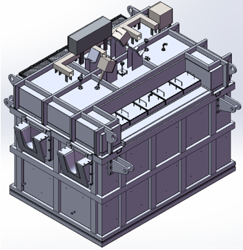
2803 Cartridge Filter Equipment
How Do You Know When a Cartridge Filter Needs to Be Replaced?
The main indicators that a cartridge filter is approaching end of service life are:
- Rising pressure differential across the filter at constant flow rate — the most reliable indicator
- Declining melt cleanliness at the casting point — increased inclusion counts, more casting defects
- Visible metal level rise upstream of the filter housing at constant casting speed
- Colour change or surface deposits on the filter element exterior during maintenance inspections
- Scheduled replacement based on tonnage processed — many operations set a maximum tonnage per filter set based on experience
Without upstream treatment, a filter on a recycled alloy line might need replacement after 5–10 tonnes. With proper upstream treatment on primary alloy, service life of 50–100 tonnes per element set is achievable.
What Happens If Cartridge Filter Preparation Is Skipped or Done Wrong?
Real consequences, not theoretical ones.
Thermal shock cracking — The most common failure mode from inadequate baking. A ceramic element that cracks during first metal contact releases ceramic fragments into the melt. Those fragments become inclusions themselves.
Hydrogen pickup from moisture — Moisture in an inadequately dried filter element and lining reacts with molten aluminum (2Al + 3H₂O → Al₂O₃ + 3H₂). The hydrogen dissolves into the melt, increasing porosity risk in castings.
Metal bypass from poor sealing — An improperly seated filter element or damaged tap-out cone allows metal to flow around the filter. The system continues running, but filtration efficiency drops to near zero.
Premature clogging from overloaded melt — If the filter is installed without upstream melt treatment and the alloy is heavily loaded with inclusions, the filter will clog quickly. The filter worked — it just filled up faster than expected because the incoming melt was too dirty.
Lining damage from improper lid handling — Opening the box cover during baking or above 100°C during cooling introduces catastrophic thermal gradients. The resulting lining cracks may not be visible externally but will cause metal penetration and insulation failure during subsequent production campaigns.
AdTech Real Case: Improving a Continuous Rod Casting Line in Turkey
A mid-sized aluminum rod producer in Turkey was running a continuous casting and rolling line with a production capacity of approximately 4.5 tonnes per hour of 8 mm EC-grade aluminum rod. The operation supplied electrical conductor manufacturers and was subject to tight conductivity specifications — any significant inclusion content in the rod affects conductivity and causes wire breakage during downstream drawing operations.
The situation before
The plant was using a basic single-stage foam filter arrangement in the launder feeding the casting wheel. The setup was originally designed for a lower production rate and had not been updated as capacity expanded. The plant was experiencing:
- Wire breakage rates at the drawing stage approximately twice the industry benchmark for EC-grade rod
- Periodic casting interruptions due to filter bypass caused by poorly fitting foam filter prints
- No upstream degassing — the melt went from the holding furnace directly to the launder and casting wheel
- Inconsistent conductivity test results, with some coils falling marginally below the minimum IACS specification
The engineering team had already tried switching foam filter suppliers twice without significant improvement, which is how they came to evaluate a different filtration approach entirely.
What was supplied and implemented
After reviewing the line layout, alloy specification, and throughput requirements, the technical team recommended a combination approach:
- One in-line degassing unit positioned between the holding furnace outlet and the launder
- A multi-tube ceramic cartridge filter system sized for 5.5 tonnes per hour installed downstream of the degassing unit
- Replacement of the existing launder lining with higher-quality ceramic fiber launder components to reduce heat loss and oxide generation during metal transfer
- A structured commissioning process including baking protocol training for the maintenance team — which turned out to be the step the plant had most consistently skipped with previous filter setups
The total equipment supplied included the degassing unit, the cartridge filter housing and initial element set, and launder lining materials for approximately 18 metres of casting launder.
Results after three months of operation
- Wire breakage rate at the drawing stage dropped by approximately 65% within the first six weeks
- Conductivity test failures effectively ceased — all production coils met IACS specification consistently
- Filter service life per element set was substantially longer than the foam filters had been
- The plant’s largest customer — a Turkish electrical cable manufacturer — reduced its incoming inspection frequency based on the improved consistency
The plant subsequently ordered a second degassing unit for a parallel casting line. The maintenance team now handles preheat, baking, and element changeover procedures independently.
For further reference on how integrated melt treatment improves aluminum rod quality, the International Aluminium Institute publishes guidance on metal quality standards for conductor-grade aluminum.
How Does Cartridge Filtration Fit Into a Modern Aluminum Melt Treatment System?
The most effective aluminum melt treatment systems treat cartridge filtration as one stage in a sequence, not a standalone solution. A typical high-quality continuous casting line might include:
- Furnace treatment — Fluxing, stirring, and settling in the holding furnace
- In-line degassing — Rotary degassing to bring hydrogen below 0.12–0.15 ml/100g
- Cartridge filtration — Fine filtration of residual inclusions after degassing
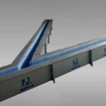
- Controlled transfer — Properly lined launders to prevent re-oxidation and temperature loss
- Casting practice — Temperature control, casting speed, and cooling management
The cartridge filter sits in the middle of this sequence. Feed it with well-treated, degassed metal and it performs well. Feed it with untreated metal and it will clog quickly, regardless of how carefully you followed the baking procedure.
This is the most important thing to understand about cartridge filter preparation — preparation is not just about the filter element itself. It is about preparing the entire melt treatment system to give the filter the conditions it needs to do its job properly.
The World Aluminium organisation provides published data on aluminum production standards and melt quality benchmarks that are useful context when setting cleanliness targets for any filtration upgrade project.
For anyone evaluating a cartridge filter installation or troubleshooting an existing system, reviewing the complete range of aluminum casting and melt treatment products gives a useful picture of how individual components — degassing, filtration, launder systems, and ceramic foam filters — fit together into a coherent treatment approach.
FAQ
1. What is a cartridge filter used for in aluminum casting?
It removes non-metallic inclusions and fine impurities from molten aluminum through surface and depth filtration before casting.
2. Why is baking required before using a cartridge filter?
Baking removes trapped moisture from the lining and filter elements and reduces thermal stress that could crack refractories during operation.
3. What temperature should the cartridge filter be baked to?
The maximum furnace gas temperature during baking is 800°C, with a controlled ramp rate to avoid thermal shock.
4. Can I open the filter box lid during the baking process?
No. Opening the lid partway through baking or above 100°C during cooling can cause lining cracks from sudden thermal shock.
5. What happens if moisture is not fully removed before operation?
Residual moisture reacts with molten aluminum to generate hydrogen gas, which increases porosity in castings.
6. How long does a cartridge filter element last?
It depends on melt condition. With proper upstream degassing, service life of 50–100 tonnes per element set is achievable.
7. Should degassing be used together with cartridge filtration?
Yes. Degassing removes dissolved hydrogen while the cartridge filter captures solid inclusions — they solve different problems.
8. How do I know when the cartridge filter needs replacement?
Rising pressure differential across the filter at constant flow rate is the most reliable indicator of element loading.
9. What causes a cartridge filter to crack during use?
Usually inadequate baking, excessive heating rate, or moisture remaining in the ceramic element before molten metal contact.
10. What is the correct flow direction for a cartridge filter?
Most cartridge filters use outside-in flow. Check manufacturer markings before installation — wrong orientation reduces performance.