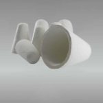
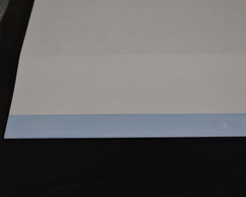
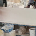
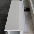
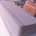
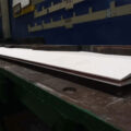
The ceramic caster tips, as the “throat component” that feeds the aluminum melt into the high-throughput continuous casting and rolling mill, play a very important role. Once problems such as clogging of the casting nozzle occur, the machine can only be shut down for replacement, resulting in production interruption, waste of manpower and material resources, and reduced production efficiency.
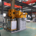
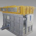
High-throughput continuous casting and rolling (HTCR) has the advantages of short process, energy saving, low production cost, etc., and has been accepted and applied by more and more enterprises in various countries. The electrolyzed aluminum liquid undergoes a high-throughput continuous casting machine and hot three-stage continuous rolling to directly form a slab of 2 mm to 8 mm, in which the flow of aluminum melt can be as high as 50t/h.
With the development and progress of science and technology, remarkable progress has been made in the treatment of aluminum melt. In the HTCR production process, a series of degassing and filtration treatments are carried out on the electrolytic aluminum liquid to remove the inclusions in the electrolytic aluminum liquid, and a cleaner aluminum liquid can be obtained. To a certain extent, to ensure that the melt passes through the casting nozzle smoothly, but the clogging of the nozzle is still the main problem faced in the production process of HTCR aluminum alloy.
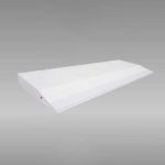
The casting-rolling process requires the internal structure of the ceramic caster tips: when the molten metal passes through, the flow line is reasonable and there is no dead angle. The molten metal should be evenly distributed between the roll gaps, and the temperature of the molten metal into the roll gap should be uniform. Through analysis and research, considering that the splitter section should gradually increase inside the nozzle, and the outlet section should be the smallest, as well as the flatness of the splitter block, it was decided to use the same height at the front and rear ends of the nozzle, and only set up and down inclined planes at the exit of the nozzle. To shrink the cross-sectional area of the nozzle outlet, the design and processing of the nozzle are greatly simplified.
Related posts:
 Distribution Caster Tips
 Twin-roll Caster Tip
 Caster Nozzle for Aluminum
 Aluminum Melt Caster Tips
 Aluminum Silicate Caster Tips
 Caster Tips
 Continuous Casting Tips and Nozzle
 Caster Feeding Nozzle
 Caster Tip and Nozzle
 Caster Tip Nozzle
 Feeding Caster Tip
 Ceramic Fiber Caster Tip
 Aluminum Casting Tips
 Continuous Aluminum Casting Tips
 Aluminum Silicate Caster Tip